Lexus ES: Speaker Circuit
DESCRIPTION
If there is a short in a speaker circuit, the stereo component amplifier assembly detects it and stops output to the speakers.
Thus sound cannot be heard from the speakers even if there is no malfunction in the stereo component amplifier assembly, DCM (telematics transceiver)* or speakers.
- *: w/ Manual (SOS) Switch
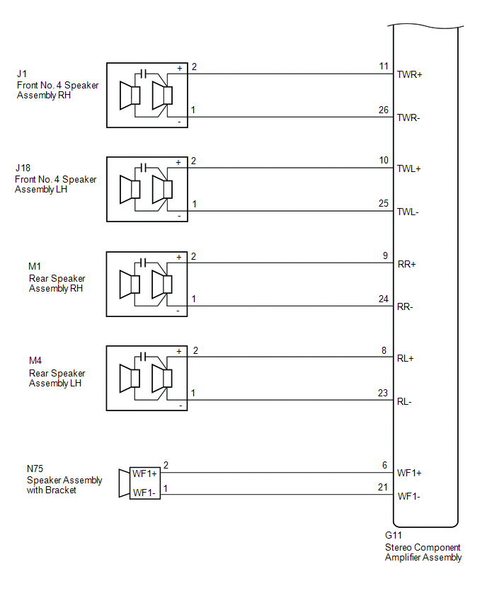
WIRING DIAGRAM
for 10 Speakers.png)
.png) for 17 Speakers
for 17 Speakers .png)
CAUTION / NOTICE / HINT
NOTICE:
-
Depending on the parts that are replaced during vehicle inspection or maintenance, performing initialization, registration or calibration may be needed. Refer to Precaution for Audio and Visual System.
Click here
.gif)
-
Before replacing the DCM (telematics transceiver), refer to Registration.
Click here
PROCEDURE
| 1. | CHECK MODEL |
(a) Choose the model to be inspected.
| Result | Proceed to |
|---|---|
| for 10 Speakers | A |
| for 17 Speakers | B |
| B | .gif) | GO TO STEP 16 |
|
.gif)
| 2. | CHECK SPEAKER (OPERATION CHECK) |
| (a) Enter the "System Check Mode" screen. Refer to Check Speaker in Operation Check. Click here |
|
.png)
(b) Perform the operation check above and determine the speaker that is not operating.
| Not Operating Speaker | Proceed to |
|---|---|
| Front No. 2 speaker assembly (w/ Manual (SOS) Switch) | A |
| Front No. 2 speaker assembly (w/o Manual (SOS) Switch) | B |
| Front No. 1 speaker assembly | C |
| Front No. 3 speaker assembly | D |
| Rear speaker assembly | E |
| Speaker assembly with bracket | F |
HINT:
If sound cannot be heard from any speaker, inspect all of them.
| B | | GO TO STEP 6 |
| C | | GO TO STEP 8 |
| D | | GO TO STEP 10 |
| E | | GO TO STEP 12 |
| F | | GO TO STEP 14 |
|
| 3. | CHECK HARNESS AND CONNECTOR (STEREO COMPONENT AMPLIFIER ASSEMBLY - DCM (TELEMATICS TRANSCEIVER) - FRONT NO. 2 SPEAKER ASSEMBLY) |
(a) Disconnect the G11 stereo component amplifier assembly connector.
(b) Disconnect the G129 DCM (telematics transceiver) connector.
(c) Disconnect the G78 and G79 front No. 2 speaker assembly connectors.
(d) Measure the resistance according to the value(s) in the table below.
Standard Resistance:
| Tester Connection | Condition | Specified Condition |
|---|---|---|
| G11-13 (FR+) - G129-1 (SPI+) | Always | Below 1 Ω |
| G11-28 (FR-) - G129-2 (SPI-) | Always | Below 1 Ω |
| G129-3 (SPO+) - G78-2 (+) | Always | Below 1 Ω |
| G129-4 (SPO-) - G78-1 (-) | Always | Below 1 Ω |
| G11-12 (FL+) - G79-2 (+) | Always | Below 1 Ω |
| G11-27 (FL-) - G79-1 (-) | Always | Below 1 Ω |
| G11-13 (FR+) or G129-1 (SPI+) - Body ground | Always | 10 kΩ or higher |
| G11-28 (FR-) or G129-2 (SPI-) - Body ground | Always | 10 kΩ or higher |
| G11-12 (FL+) or G79-2 (+) - Body ground | Always | 10 kΩ or higher |
| G11-27 (FL-) or G79-1 (-) - Body ground | Always | 10 kΩ or higher |
| G129-3 (SPO+) or G78-2 (+) - Body ground | Always | 10 kΩ or higher |
| G129-4 (SPO-) or G78-1 (-) - Body ground | Always | 10 kΩ or higher |
| NG | | REPAIR OR REPLACE HARNESS OR CONNECTOR |
|
| 4. | REPLACE FRONT NO. 2 SPEAKER ASSEMBLY |
(a) Remove the front No. 2 speaker assembly.
Click here
(b) Inspect the front No. 2 speaker assembly.
Click here
OK:
Malfunction disappears.
| OK | | END |
|
| 5. | INSPECT DCM (TELEMATICS TRANSCEIVER) |
(a) Remove the DCM (telematics transceiver).
Click here
| (b) Measure the resistance according to the value(s) in the table below. Standard Resistance:
|
|
.png)
| OK | | PROCEED TO NEXT SUSPECTED AREA SHOWN IN PROBLEM SYMPTOMS TABLE |
| NG | | REPLACE DCM (TELEMATICS TRANSCEIVER) |
| 6. | CHECK HARNESS AND CONNECTOR (STEREO COMPONENT AMPLIFIER ASSEMBLY - FRONT NO. 2 SPEAKER ASSEMBLY) |
(a) Disconnect the G11 stereo component amplifier assembly connector.
(b) Disconnect the G78 and G79 front No. 2 speaker assembly connectors.
(c) Measure the resistance according to the value(s) in the table below.
Standard Resistance:
| Tester Connection | Condition | Specified Condition |
|---|---|---|
| G11-13 (FR+) - G78-2 (+) | Always | Below 1 Ω |
| G11-28 (FR-) - G78-1 (-) | Always | Below 1 Ω |
| G11-12 (FL+) - G79-2 (+) | Always | Below 1 Ω |
| G11-27 (FL-) - G79-1 (-) | Always | Below 1 Ω |
| G11-13 (FR+) or G78-2 (+) - Body ground | Always | 10 kΩ or higher |
| G11-28 (FR-) or G78-1 (-) - Body ground | Always | 10 kΩ or higher |
| G11-12 (FL+) or G79-2 (+) - Body ground | Always | 10 kΩ or higher |
| G11-27 (FL-) or G79-1 (-) - Body ground | Always | 10 kΩ or higher |
| NG | | REPAIR OR REPLACE HARNESS OR CONNECTOR |
|
| 7. | REPLACE FRONT NO. 2 SPEAKER ASSEMBLY |
(a) Remove the front No. 2 speaker assembly.
Click here
(b) Inspect the front No. 2 speaker assembly.
Click here
OK:
Malfunction disappears.
| OK | | END |
| NG | | PROCEED TO NEXT SUSPECTED AREA SHOWN IN PROBLEM SYMPTOMS TABLE |
| 8. | CHECK HARNESS AND CONNECTOR (STEREO COMPONENT AMPLIFIER ASSEMBLY - FRONT NO. 1 SPEAKER ASSEMBLY) |
(a) Disconnect the G11 stereo component amplifier assembly connector.
(b) Disconnect the J2 and J19 front No. 1 speaker assembly connectors.
(c) Measure the resistance according to the value(s) in the table below.
Standard Resistance:
| Tester Connection | Condition | Specified Condition |
|---|---|---|
| G11-5 (WFR+) - J2-2 (WF+) | Always | Below 1 Ω |
| G11-20 (WFR-) - J2-1 (WF-) | Always | Below 1 Ω |
| G11-4 (WFL+) - J19-2 (WF+) | Always | Below 1 Ω |
| G11-19 (WFL-) - J19-1 (WF-) | Always | Below 1 Ω |
| G11-5 (WFR+) or J2-2 (WF+) - Body ground | Always | 10 kΩ or higher |
| G11-20 (WFR-) or J2-1 (WF-) - Body ground | Always | 10 kΩ or higher |
| G11-4 (WFL+) or J19-2 (WF+) - Body ground | Always | 10 kΩ or higher |
| G11-19 (WFL-) or J19-1 (WF-) - Body ground | Always | 10 kΩ or higher |
| NG | | REPAIR OR REPLACE HARNESS OR CONNECTOR |
|
| 9. | INSPECT FRONT NO. 1 SPEAKER ASSEMBLY |
(a) Remove the front No. 1 speaker assembly.
Click here
(b) Inspect the front No. 1 speaker assembly.
Click here
| OK | | PROCEED TO NEXT SUSPECTED AREA SHOWN IN PROBLEM SYMPTOMS TABLE |
| NG | | REPLACE FRONT NO. 1 SPEAKER ASSEMBLY |
| 10. | CHECK HARNESS AND CONNECTOR (STEREO COMPONENT AMPLIFIER ASSEMBLY - FRONT NO. 3 SPEAKER ASSEMBLY) |
(a) Disconnect the G11 stereo component amplifier assembly connector.
(b) Disconnect the H6 front No. 3 speaker assembly connector.
(c) Measure the resistance according to the value(s) in the table below.
Standard Resistance:
| Tester Connection | Condition | Specified Condition |
|---|---|---|
| G11-7 (CTR+) - H6-2 (+) | Always | Below 1 Ω |
| G11-22 (CTR-) - H6-1 (-) | Always | Below 1 Ω |
| G11-7 (CTR+) or H6-2 (+) - Body ground | Always | 10 kΩ or higher |
| G11-22 (CTR-) or H6-1 (-) - Body ground | Always | 10 kΩ or higher |
| NG | | REPAIR OR REPLACE HARNESS OR CONNECTOR |
|
| 11. | INSPECT FRONT NO. 3 SPEAKER ASSEMBLY |
(a) Remove the front No. 3 speaker assembly.
Click here
(b) Inspect the front No. 3 speaker assembly.
Click here
| OK | | PROCEED TO NEXT SUSPECTED AREA SHOWN IN PROBLEM SYMPTOMS TABLE |
| NG | | REPLACE FRONT NO. 3 SPEAKER ASSEMBLY |
| 12. | CHECK HARNESS AND CONNECTOR (STEREO COMPONENT AMPLIFIER ASSEMBLY - REAR SPEAKER ASSEMBLY) |
(a) Disconnect the G11 stereo component amplifier assembly connector.
(b) Disconnect the M1 and L6 rear speaker assembly connectors. (Door Trim Wood Panel Type, w/o Ambient Light)
(c) Disconnect the M1 and M4 rear speaker assembly connectors. (Except Door Trim Wood Panel Type)
(d) Disconnect the M1 and M4 rear speaker assembly connectors. (w/ Ambient Light)
(e) Measure the resistance according to the value(s) in the table below.
Standard Resistance:
| Tester Connection | Condition | Specified Condition |
|---|---|---|
| G11-9 (RR+) - M1-2 (+) | Always | Below 1 Ω |
| G11-24 (RR-) - M1-1 (-) | Always | Below 1 Ω |
| G11-8 (RL+) - L6-2 (+)*1 | Always | Below 1 Ω |
| G11-8 (RL+) - M4-2 (+)*2, *3 | Always | Below 1 Ω |
| G11-23 (RL-) - L6-1 (-)*1 | Always | Below 1 Ω |
| G11-23 (RL-) - M4-1 (-)*2, *3 | Always | Below 1 Ω |
| G11-9 (RR+) or M1-2 (+) - Body ground | Always | 10 kΩ or higher |
| G11-24 (RR-) or M1-1 (-) - Body ground | Always | 10 kΩ or higher |
| G11-8 (RL+) or L6-2 (+) - Body ground*1 | Always | 10 kΩ or higher |
| G11-8 (RL+) or M4-2 (+) - Body ground*2, *3 | Always | 10 kΩ or higher |
| G11-23 (RL-) or L6-1 (-) - Body ground*1 | Always | 10 kΩ or higher |
| G11-23 (RL-) or M4-1 (-) - Body ground*2, *3 | Always | 10 kΩ or higher |
- *1: Door Trim Wood Panel Type, w/o Ambient Light
- *2: Except Door Trim Wood Panel Type
- *3: w/ Ambient Light
| NG | | REPAIR OR REPLACE HARNESS OR CONNECTOR |
|
| 13. | INSPECT REAR SPEAKER ASSEMBLY |
(a) Remove the rear speaker assembly.
Click here
(b) Inspect the rear speaker assembly.
Click here
| OK | | PROCEED TO NEXT SUSPECTED AREA SHOWN IN PROBLEM SYMPTOMS TABLE |
| NG | | REPLACE REAR SPEAKER ASSEMBLY |
| 14. | CHECK HARNESS AND CONNECTOR (STEREO COMPONENT AMPLIFIER ASSEMBLY - SPEAKER ASSEMBLY WITH BRACKET) |
(a) Disconnect the G11 stereo component amplifier assembly connector.
(b) Disconnect the N75 speaker assembly with bracket connector.
(c) Measure the resistance according to the value(s) in the table below.
Standard Resistance:
| Tester Connection | Condition | Specified Condition |
|---|---|---|
| G11-6 (WF1+) - N75-2 (WF1+) | Always | Below 1 Ω |
| G11-21 (WF1-) - N75-1 (WF1-) | Always | Below 1 Ω |
| G11-6 (WF1+) or N75-2 (WF1+) - Body ground | Always | 10 kΩ or higher |
| G11-21 (WF1-) or N75-1 (WF1-) - Body ground | Always | 10 kΩ or higher |
| NG | | REPAIR OR REPLACE HARNESS OR CONNECTOR |
|
| 15. | INSPECT SPEAKER ASSEMBLY WITH BRACKET |
(a) Remove the speaker assembly with bracket.
Click here
(b) Inspect the speaker assembly with bracket.
Click here
| OK | | PROCEED TO NEXT SUSPECTED AREA SHOWN IN PROBLEM SYMPTOMS TABLE |
| NG | | REPLACE SPEAKER ASSEMBLY WITH BRACKET |
| 16. | CHECK SPEAKER (OPERATION CHECK) |
| (a) Enter the "System Check Mode" screen. Refer to Check Speaker in Operation Check. Click here |
|
(b) Perform the operation check above and determine the speaker that is not operating.
| Not Operating Speaker | Proceed to |
|---|---|
| Front No. 2 speaker assembly (w/ Manual (SOS) Switch) | A |
| Front No. 2 speaker assembly (w/o Manual (SOS) Switch) | B |
| Front No. 1 speaker assembly | C |
| Front No. 3 speaker assembly | D |
| Front No. 4 speaker assembly | E |
| Rear speaker assembly | F |
| Speaker assembly with bracket | G |
HINT:
If sound cannot be heard from any speaker, inspect all of them.
| B | | GO TO STEP 20 |
| C | | GO TO STEP 22 |
| D | | GO TO STEP 24 |
| E | | GO TO STEP 26 |
| F | | GO TO STEP 28 |
| G | | GO TO STEP 30 |
|
| 17. | CHECK HARNESS AND CONNECTOR (STEREO COMPONENT AMPLIFIER ASSEMBLY - DCM (TELEMATICS TRANSCEIVER) - FRONT NO. 2 SPEAKER ASSEMBLY) |
(a) Disconnect the G11 stereo component amplifier assembly connector.
(b) Disconnect the G129 DCM (telematics transceiver) connector.
(c) Disconnect the G78 and G79 front No. 2 speaker assembly connectors.
(d) Measure the resistance according to the value(s) in the table below.
Standard Resistance:
| Tester Connection | Condition | Specified Condition |
|---|---|---|
| G11-13 (FR+) - G129-1 (SPI+) | Always | Below 1 Ω |
| G11-28 (FR-) - G129-2 (SPI-) | Always | Below 1 Ω |
| G129-3 (SPO+) - G78-2 (+) | Always | Below 1 Ω |
| G129-4 (SPO-) - G78-1 (-) | Always | Below 1 Ω |
| G11-12 (FL+) - G79-2 (+) | Always | Below 1 Ω |
| G11-27 (FL-) - G79-1 (-) | Always | Below 1 Ω |
| G11-13 (FR+) or G129-1 (SPI+) - Body ground | Always | 10 kΩ or higher |
| G11-28 (FR-) or G129-2 (SPI-) - Body ground | Always | 10 kΩ or higher |
| G11-12 (FL+) or G79-2 (+) - Body ground | Always | 10 kΩ or higher |
| G11-27 (FL-) or G79-1 (-) - Body ground | Always | 10 kΩ or higher |
| G129-3 (SPO+) or G78-2 (+) - Body ground | Always | 10 kΩ or higher |
| G129-4 (SPO-) or G78-1 (-) - Body ground | Always | 10 kΩ or higher |
| NG | | REPAIR OR REPLACE HARNESS OR CONNECTOR |
|
| 18. | REPLACE FRONT NO.2 SPEAKER ASSEMBLY |
(a) Remove the front No. 2 speaker assembly.
Click here
(b) Inspect the front No. 2 speaker assembly.
Click here
OK:
Malfunction disappears.
| OK | | END |
|
| 19. | INSPECT DCM (TELEMATICS TRANSCEIVER) |
(a) Remove the DCM (telematics transceiver).
Click here
| (b) Measure the resistance according to the value(s) in the table below. Standard Resistance:
|
|
| OK | | PROCEED TO NEXT SUSPECTED AREA SHOWN IN PROBLEM SYMPTOMS TABLE |
| NG | | REPLACE DCM (TELEMATICS TRANSCEIVER) |
| 20. | CHECK HARNESS AND CONNECTOR (STEREO COMPONENT AMPLIFIER ASSEMBLY - FRONT NO. 2 SPEAKER ASSEMBLY) |
(a) Disconnect the G11 stereo component amplifier assembly connector.
(b) Disconnect the G78 and G79 front No. 2 speaker assembly connectors.
(c) Measure the resistance according to the value(s) in the table below.
Standard Resistance:
| Tester Connection | Condition | Specified Condition |
|---|---|---|
| G11-13 (FR+) - G78-2 (+) | Always | Below 1 Ω |
| G11-28 (FR-) - G78-1 (-) | Always | Below 1 Ω |
| G11-12 (FL+) - G79-2 (+) | Always | Below 1 Ω |
| G11-27 (FL-) - G79-1 (-) | Always | Below 1 Ω |
| G11-13 (FR+) or G78-2 (+) - Body ground | Always | 10 kΩ or higher |
| G11-28 (FR-) or G78-1 (-) - Body ground | Always | 10 kΩ or higher |
| G11-12 (FL+) or G79-2 (+) - Body ground | Always | 10 kΩ or higher |
| G11-27 (FL-) or G79-1 (-) - Body ground | Always | 10 kΩ or higher |
| NG | | REPAIR OR REPLACE HARNESS OR CONNECTOR |
|
| 21. | REPLACE FRONT NO. 2 SPEAKER ASSEMBLY |
(a) Remove the front No. 2 speaker assembly.
Click here
(b) Inspect the front No. 2 speaker assembly.
Click here
OK:
Malfunction disappears.
| OK | | END |
| NG | | PROCEED TO NEXT SUSPECTED AREA SHOWN IN PROBLEM SYMPTOMS TABLE |
| 22. | CHECK HARNESS AND CONNECTOR (STEREO COMPONENT AMPLIFIER ASSEMBLY - FRONT NO. 1 SPEAKER ASSEMBLY) |
(a) Disconnect the G11 stereo component amplifier assembly connector.
(b) Disconnect the J2 and J19 front No. 1 speaker assembly connectors.
(c) Measure the resistance according to the value(s) in the table below.
Standard Resistance:
| Tester Connection | Condition | Specified Condition |
|---|---|---|
| G11-5 (WFR+) - J2-2 (WF+) | Always | Below 1 Ω |
| G11-20 (WFR-) - J2-1 (WF-) | Always | Below 1 Ω |
| G11-4 (WFL+) - J19-2 (WF+) | Always | Below 1 Ω |
| G11-19 (WFL-) - J19-1 (WF-) | Always | Below 1 Ω |
| G11-5 (WFR+) or J2-2 (WF+) - Body ground | Always | 10 kΩ or higher |
| G11-20 (WFR-) or J2-1 (WF-) - Body ground | Always | 10 kΩ or higher |
| G11-4 (WFL+) or J19-2 (WF+) - Body ground | Always | 10 kΩ or higher |
| G11-19 (WFL-) or J19-1 (WF-) - Body ground | Always | 10 kΩ or higher |
| NG | | REPAIR OR REPLACE HARNESS OR CONNECTOR |
|
| 23. | INSPECT FRONT NO. 1 SPEAKER ASSEMBLY |
(a) Remove the front No. 1 speaker assembly.
Click here
(b) Inspect the front No. 1 speaker assembly.
Click here
| OK | | PROCEED TO NEXT SUSPECTED AREA SHOWN IN PROBLEM SYMPTOMS TABLE |
| NG | | REPLACE FRONT NO. 1 SPEAKER ASSEMBLY |
| 24. | CHECK HARNESS AND CONNECTOR (STEREO COMPONENT AMPLIFIER ASSEMBLY - FRONT NO. 3 SPEAKER ASSEMBLY) |
(a) Disconnect the G11 stereo component amplifier assembly connector.
(b) Disconnect the H6 front No. 3 speaker assembly connector.
(c) Measure the resistance according to the value(s) in the table below.
Standard Resistance:
| Tester Connection | Condition | Specified Condition |
|---|---|---|
| G11-7 (CTR+) - H6-2 (+) | Always | Below 1 Ω |
| G11-22 (CTR-) - H6-1 (-) | Always | Below 1 Ω |
| G11-7 (CTR+) or H6-2 (+) - Body ground | Always | 10 kΩ or higher |
| G11-22 (CTR-) or H6-1 (-) - Body ground | Always | 10 kΩ or higher |
| NG | | REPAIR OR REPLACE HARNESS OR CONNECTOR |
|
| 25. | REPLACE FRONT NO. 3 SPEAKER ASSEMBLY |
(a) Remove the front No. 3 speaker assembly.
Click here
(b) Inspect the front No. 3 speaker assembly.
Click here
OK:
Malfunction disappears.
| OK | | END |
| NG | | PROCEED TO NEXT SUSPECTED AREA SHOWN IN PROBLEM SYMPTOMS TABLE |
| 26. | CHECK HARNESS AND CONNECTOR (STEREO COMPONENT AMPLIFIER ASSEMBLY - FRONT NO. 4 SPEAKER ASSEMBLY) |
(a) Disconnect the G11 stereo component amplifier assembly connector.
(b) Disconnect the J1 and J18 front No. 4 speaker assembly connectors.
(c) Measure the resistance according to the value(s) in the table below.
Standard Resistance:
| Tester Connection | Condition | Specified Condition |
|---|---|---|
| G11-11 (TWR+) - J1-2 (+) | Always | Below 1 Ω |
| G11-26 (TWR-) - J1-1 (-) | Always | Below 1 Ω |
| G11-10 (TWL+) - J18-2 (+) | Always | Below 1 Ω |
| G11-25 (TWL-) - J18-1 (-) | Always | Below 1 Ω |
| G11-11 (TWR+) or J1-2 (+) - Body ground | Always | 10 kΩ or higher |
| G11-26 (TWR-) or J1-1 (-) - Body ground | Always | 10 kΩ or higher |
| G11-10 (TWL+) or J18-2 (+) - Body ground | Always | 10 kΩ or higher |
| G11-25 (TWL-) or J18-1 (-) - Body ground | Always | 10 kΩ or higher |
| NG | | REPAIR OR REPLACE HARNESS OR CONNECTOR |
|
| 27. | REPLACE FRONT NO. 4 SPEAKER ASSEMBLY |
(a) Remove the front No. 4 speaker assembly.
Click here
(b) Inspect the front No. 4 speaker assembly.
Click here
OK:
Malfunction disappears.
| OK | | END |
| NG | | PROCEED TO NEXT SUSPECTED AREA SHOWN IN PROBLEM SYMPTOMS TABLE |
| 28. | CHECK HARNESS AND CONNECTOR (STEREO COMPONENT AMPLIFIER ASSEMBLY - REAR SPEAKER ASSEMBLY) |
(a) Disconnect the G11 stereo component amplifier assembly connector.
(b) Disconnect the M1 and M4 rear speaker assembly connectors.
(c) Measure the resistance according to the value(s) in the table below.
Standard Resistance:
| Tester Connection | Condition | Specified Condition |
|---|---|---|
| G11-9 (RR+) - M1-2 (+) | Always | Below 1 Ω |
| G11-24 (RR-) - M1-1 (-) | Always | Below 1 Ω |
| G11-8 (RL+) - M4-2 (+) | Always | Below 1 Ω |
| G11-23 (RL-) - M4-1 (-) | Always | Below 1 Ω |
| G11-9 (RR+) or M1-2 (+) - Body ground | Always | 10 kΩ or higher |
| G11-24 (RR-) or M1-1 (-) - Body ground | Always | 10 kΩ or higher |
| G11-8 (RL+) or M4-2 (+) - Body ground | Always | 10 kΩ or higher |
| G11-23 (RL-) or M4-1 (-) - Body ground | Always | 10 kΩ or higher |
| NG | | REPAIR OR REPLACE HARNESS OR CONNECTOR |
|
| 29. | REPLACE REAR SPEAKER ASSEMBLY |
(a) Remove the rear speaker assembly.
Click here
(b) Inspect the rear speaker assembly.
Click here
OK:
Malfunction disappears.
| OK | | END |
| NG | | PROCEED TO NEXT SUSPECTED AREA SHOWN IN PROBLEM SYMPTOMS TABLE |
| 30. | CHECK HARNESS AND CONNECTOR (STEREO COMPONENT AMPLIFIER ASSEMBLY - SPEAKER ASSEMBLY WITH BRACKET) |
(a) Disconnect the G11 stereo component amplifier assembly connector.
(b) Disconnect the N75 speaker assembly with bracket connector.
(c) Measure the resistance according to the value(s) in the table below.
Standard Resistance:
| Tester Connection | Condition | Specified Condition |
|---|---|---|
| G11-6 (WF1+) - N75-2 (WF1+) | Always | Below 1 Ω |
| G11-21 (WF1-) - N75-1 (WF1-) | Always | Below 1 Ω |
| G11-6 (WF1+) or N75-2 (WF1+) - Body ground | Always | 10 kΩ or higher |
| G11-21 (WF1-) or N75-1 (WF1-) - Body ground | Always | 10 kΩ or higher |
| NG | | REPAIR OR REPLACE HARNESS OR CONNECTOR |
|
| 31. | INSPECT SPEAKER ASSEMBLY WITH BRACKET |
(a) Remove the speaker assembly with bracket.
Click here
(b) Inspect the speaker assembly with bracket.
Click here
| OK | | PROCEED TO NEXT SUSPECTED AREA SHOWN IN PROBLEM SYMPTOMS TABLE |
| NG | | REPLACE SPEAKER ASSEMBLY WITH BRACKET |
READ NEXT:
 Steering Pad Switch Circuit
DESCRIPTION This circuit sends an operation signal from the steering pad switch assembly to the radio receiver assembly. If there is an open in the circuit, the audio system cannot be operated using t
Stereo Jack Adapter Light does not Illuminate
DESCRIPTION Power is supplied to the No. 1 stereo jack adapter assembly illumination from the radio receiver assembly. WIRING DIAGRAM CAUTION / NOTICE / HINT NOTICE:
Depending on the parts that ar
Switch Lights of Remote Touch Always Illuminate or cannot be Controlled Using Rheostat
DESCRIPTION Power is supplied to the remote touch (remote operation controller assembly) illumination when the light control switch is in the tail or head position. HINT:
When the remote touch (rem
SEE MORE:
Terminals Of Ecu
TERMINALS OF ECU CHECK SWING GRILLE ACTUATOR ASSEMBLY (a) Disconnect the z23 swing grille actuator assembly connector. (b) Measure the voltage and resistance according to the value(s) in the table below. HINT: Measure the values on the wire harness side with the connector disconnected. Tester Co
Active Noise Control Ecu
ComponentsCOMPONENTS ILLUSTRATION *A for HV Model - - *1 STEREO COMPONENT EQUALIZER ASSEMBLY *2 VEHICLE APPROACHING SPEAKER CONTROLLER N*m (kgf*cm, ft.*lbf): Specified torque - - InstallationINSTALLATION PROCEDURE 1. INSTALL STEREO COMPONENT EQUALIZER ASSEMBLY (a)
