Lexus ES: Steering Pad Switch Circuit
DESCRIPTION
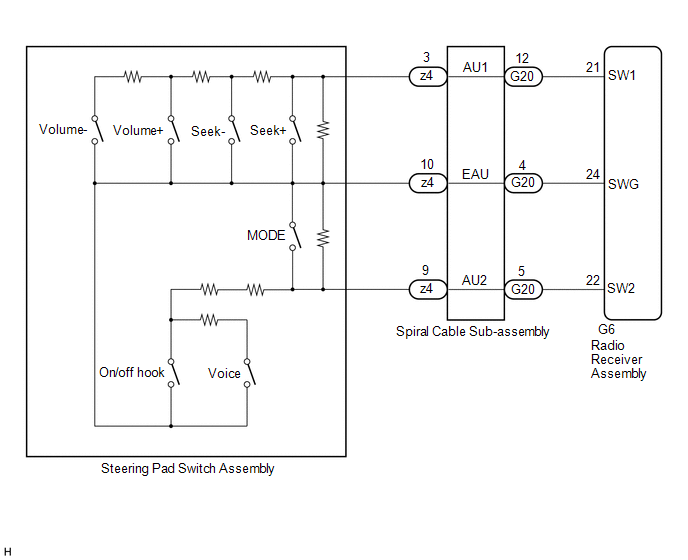
This circuit sends an operation signal from the steering pad switch assembly to the radio receiver assembly.
If there is an open in the circuit, the audio system cannot be operated using the steering pad switch assembly.
If there is a short in the circuit, the same condition as when a switch is continuously depressed occurs.
Therefore, the radio receiver assembly cannot be operated using the steering pad switch assembly, and the radio receiver assembly itself will not function.
WIRING DIAGRAM
CAUTION / NOTICE / HINT
NOTICE:
The vehicle is equipped with a Supplemental Restraint System (SRS) which includes components such as airbags. Before servicing (including removal or installation of parts), be sure to read the precaution for Supplemental Restraint System.
Click here .gif)
PROCEDURE
| 1. | CHECK HARNESS AND CONNECTOR (STEERING PAD SWITCH SIGNAL) |
(a) Disconnect the G6 radio receiver assembly connector.
(b) Measure the resistance according to the value(s) in the table below.
Standard Resistance:
| Tester Connection | Condition | Specified Condition |
|---|---|---|
| G6-21 (SW1) - G6-24 (SWG) | No switch pushed | 95 to 105 kΩ |
| Seek+ switch pushed | Below 2.5 Ω | |
| Seek- switch pushed | 313 to 345 Ω | |
| Volume+ switch pushed | 950 to 1050 Ω | |
| Volume- switch pushed | 2955 to 3265 Ω | |
| G6-22 (SW2) - G6-24 (SWG) | No switch pushed | 95 to 105 kΩ |
| MODE switch pushed | Below 2.5 Ω | |
| On/off hook switch pushed | 950 to 1050 Ω | |
| Voice switch pushed | 2955 to 3265 Ω |
| OK | .gif) | PROCEED TO NEXT SUSPECTED AREA SHOWN IN PROBLEM SYMPTOMS TABLE |
|
.gif)
| 2. | INSPECT STEERING PAD SWITCH ASSEMBLY |
(a) Remove the steering pad switch assembly.
Click here
(b) Inspect the steering pad switch assembly.
Click here
| NG | | REPLACE STEERING PAD SWITCH ASSEMBLY |
|
| 3. | INSPECT SPIRAL CABLE SUB-ASSEMBLY |
(a) Remove the spiral cable sub-assembly.
Click here
(b) Inspect the spiral cable sub-assembly.
Click here
| OK | | REPAIR OR REPLACE HARNESS OR CONNECTOR (RADIO RECEIVER ASSEMBLY - SPIRAL CABLE SUB-ASSEMBLY) |
| NG | | REPLACE SPIRAL CABLE SUB-ASSEMBLY |
READ NEXT:
 Stereo Jack Adapter Light does not Illuminate
DESCRIPTION Power is supplied to the No. 1 stereo jack adapter assembly illumination from the radio receiver assembly. WIRING DIAGRAM CAUTION / NOTICE / HINT NOTICE:
Depending on the parts that ar
Switch Lights of Remote Touch Always Illuminate or cannot be Controlled Using Rheostat
DESCRIPTION Power is supplied to the remote touch (remote operation controller assembly) illumination when the light control switch is in the tail or head position. HINT:
When the remote touch (rem
Switch Lights of Remote Touch do not Illuminate
DESCRIPTION Power is supplied to the remote touch (remote operation controller assembly) illumination when the light control switch is in the tail or head position. WIRING DIAGRAM CAUTION / NOTICE /
SEE MORE:
Removal
REMOVAL CAUTION / NOTICE / HINT The necessary procedures (adjustment, calibration, initialization or registration) that must be performed after parts are removed and installed, or replaced during windshield glass sub-assembly removal/installation are shown below. Necessary Procedure After Parts Remo
Horn
ComponentsCOMPONENTS ILLUSTRATION *1 COOL AIR INTAKE DUCT SEAL *2 HIGH PITCHED HORN ASSEMBLY *3 LOW PITCHED HORN ASSEMBLY - - N*m (kgf*cm, ft.*lbf): Specified torque - - RemovalREMOVAL PROCEDURE 1. REMOVE COOL AIR INTAKE DUCT SEAL Click here 2. REMOVE HIGH PITC
