Lexus ES: Shut Down Signal Circuit
DESCRIPTION
The cause of the malfunction may be a shutdown signal.
Check whether there is a shutdown signal +B short circuit.
Related Parts Check| Area | Inspection |
|---|---|
| HSDN terminal | Check that the HSDN terminal voltage decreases to check for an open or short circuit while READY off (IG ON). |
| Hybrid vehicle control ECU, inverter, wire harness | Check for open or short circuit in hybrid vehicle control ECU, inverter and wire harness. |
SYSTEM DESCRIPTION
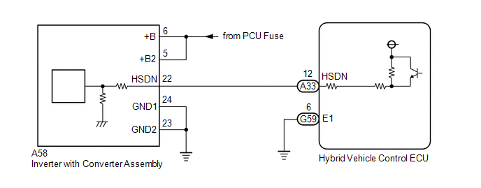
Power supply to the motor is cut off due to a shutdown signal sent from the hybrid vehicle control ECU to the motor generator control ECU (MG ECU).
WIRING DIAGRAM
CAUTION / NOTICE / HINT
This diagnostic procedure is referenced to in the diagnostic procedure of several DTCs.
If the result of this diagnostic procedure is normal, proceed as directed in the procedure for the DTC.
CAUTION:
-
Before the following operations are conducted, take precautions to prevent electric shock by turning the power switch off, wearing insulated gloves, and removing the service plug grip from HV battery.
.png)
- Inspecting the high-voltage system
- Disconnecting the low voltage connector of the inverter with converter assembly
- Disconnecting the low voltage connector of the HV battery
-
To prevent electric shock, make sure to remove the service plug grip to cut off the high voltage circuit before servicing the vehicle.
.png)
-
After removing the service plug grip from the HV battery, put it in your pocket to prevent other technicians from accidentally reconnecting it while you are working on the high-voltage system.
.png)
-
After removing the service plug grip, wait for at least 10 minutes before touching any of the high-voltage connectors or terminals. After waiting for 10 minutes, check the voltage at the terminals in the inspection point in the inverter with converter assembly. The voltage should be 0 V before beginning work.
.png)
*a
Without waiting for 10 minutes
Click here
.gif)
HINT:
Waiting for at least 10 minutes is required to discharge the high-voltage capacitor inside the inverter with converter assembly.
NOTICE:
After turning the power switch off, waiting time may be required before disconnecting the cable from the negative (-) auxiliary battery terminal. Therefore, make sure to read the disconnecting the cable from the negative (-) auxiliary battery terminal notices before proceeding with work.
Click here
PROCEDURE
| 1. | CHECK HYBRID VEHICLE CONTROL ECU |
(a) Turn the power switch on (IG).
| (b) Measure the voltage according to the value(s) in the table below. Standard Voltage:
|
|
(c) Turn the power switch off.
| OK | .gif) | SHUTDOWN SIGNAL CIRCUIT NORMAL (PERFORM NEXT STEP FOR REFERENCED DTC) |
|
.gif)
| 2. | CHECK HARNESS AND CONNECTOR (HYBRID VEHICLE CONTROL ECU - INVERTER WITH CONVERTER ASSEMBLY) |
CAUTION:
Be sure to wear insulated gloves.
(a) Check that the service plug grip is not installed.
NOTICE:
After removing the service plug grip, do not turn the power switch on (READY), unless instructed by the repair manual because this may cause a malfunction.
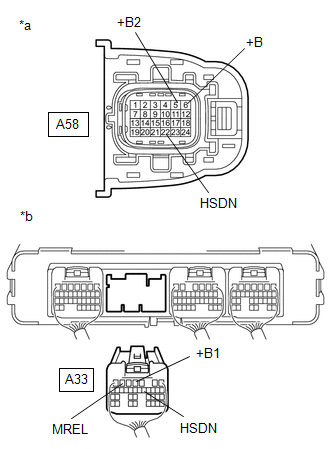
(b) Disconnect the A58 inverter with converter assembly connector.
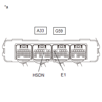
(c) Disconnect the A33 hybrid vehicle control ECU connector.
(d) Connect the cable to the negative (-) auxiliary battery terminal.
(e) Turn the power switch on (IG).
| (f) Measure the voltage according to the value(s) in the table below. Standard Voltage:
NOTICE: Turning the power switch on (IG) with the hybrid vehicle control ECU and inverter with converter assembly connector disconnected causes other DTCs to be stored. Clear the DTCs after performing this inspection. |
|
(g) Turn the power switch off.
(h) Disconnect the cable from the negative (-) auxiliary battery terminal, and wait for 2 minutes or more.
(i) Measure the resistance according to the value(s) in the table below.
Standard Resistance:
| Tester Connection | Condition | Specified Condition |
|---|---|---|
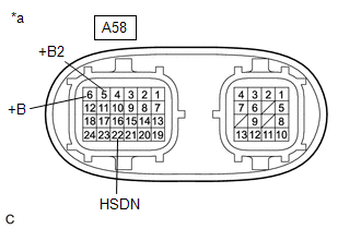
| A58-22 (HSDN) - A58-6 (+B) | Power switch off | 10 kΩ or higher |
| A58-22 (HSDN) - A58-5 (+B2) | Power switch off | 10 kΩ or higher |
| A33-12 (HSDN) - A33-4 (+B1) | Power switch off | 10 kΩ or higher |
| A33-12 (HSDN) - A33-6 (MREL) | Power switch off | 10 kΩ or higher |
(j) Reconnect the A33 hybrid vehicle control ECU connector.
(k) Reconnect the A58 inverter with converter assembly connector.
| NG | | REPAIR OR REPLACE HARNESS OR CONNECTOR |
|
| 3. | CHECK INVERTER WITH CONVERTER ASSEMBLY |
CAUTION:
Be sure to wear insulated gloves.
(a) Check that the service plug grip is not installed.
NOTICE:
After removing the service plug grip, do not turn the power switch on (READY), unless instructed by the repair manual because this may cause a malfunction.
(b) Disconnect the A58 inverter with converter assembly connector.
| (c) Measure the resistance according to the value(s) in the table below. Standard Resistance:
|
|
(d) Reconnect the A58 inverter with converter assembly connector.
| OK | | REPLACE HYBRID VEHICLE CONTROL ECU |
| NG | | REPLACE INVERTER WITH CONVERTER ASSEMBLY |
READ NEXT:
 Inverter Low-voltage Circuit
DESCRIPTION The cause of the malfunction may be the low-voltage circuit. Check whether there is an open circuit in the inverter +B low-voltage power source system or a problem in the communication bet
HV Battery High-voltage Line Circuit
DESCRIPTION The cause of the malfunction may be the HV battery high-voltage line circuit. Check the continuity in the high-voltage line from the HV battery to the inverter. Check the connection condit
SEE MORE:
Red Indicator Remains On
DESCRIPTION This means that the DCM (telematics transceiver) has detected a malfunction in the safety connect system and stored a DTC or specific vehicle control history (RoB) Code. PROCEDURE 1. CHECK DTC (a) Turn the engine switch off. (b) Connect the Techstream to the DLC3. (c) Turn the e
Definition Of Terms
DEFINITION OF TERMS Term Definition Monitor Description Description of what the ECM monitors and how it detects malfunctions (monitoring purpose and details). Related DTCs Group of diagnostic trouble codes that are output by the ECM based on the same malfunction detection logic.
