Lexus ES: Short to GND or Open in Buzzer (C1ABE)
DESCRIPTION
- DTC C1ABE is stored when the blind spot monitor sensor LH detects a short to ground or open in the RCTA buzzer (blind spot monitor buzzer) circuit.
| DTC No. | Detection Item | DTC Detection Condition | Trouble Area |
|---|---|---|---|
| C1ABE | Short to GND or Open in Buzzer | Both of the following conditions are met:
|
|
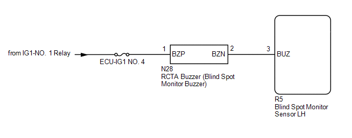
WIRING DIAGRAM
CAUTION / NOTICE / HINT
NOTICE:
- When checking for DTCs, make sure that the blind spot monitor system is turned on.
- Inspect the fuses for circuits related to this system before performing the following procedure.
PROCEDURE
| 1. | READ VALUE USING TECHSTREAM (BLIND SPOT MONITOR SENSOR LH STATUS) |
(a) Connect the Techstream to the DLC3.
(b) Turn the power switch on (IG).
(c) Turn the Techstream on.
(d) Enter the following menus: Body Electrical / Blind Spot Monitor Slave / Data List.
(e) Read the Data List according to the display on the Techstream.
Body Electrical > Blind Spot Monitor Slave > Data List| Tester Display | Measurement Item | Range | Normal Condition | Diagnostic Note |
|---|---|---|---|---|
| Buzzer Connection | Status of the buzzer connection | Valid or Invalid | Valid: Buzzer connection is valid Invalid: Buzzer connection is invalid | - |
| Slave Side RCTA Function | Switches the RCTA function on and off | OFF or ON | OFF: RCTA function off ON: RCTA function on | - |
| Tester Display |
|---|
| Buzzer Connection |
| Slave Side RCTA Function |
| Result | Proceed to |
|---|---|
| "Valid" and "ON" is displayed for all items. | A |
| "Invalid" or "OFF" is displayed. | B |
| B | .gif) | REPLACE BLIND SPOT MONITOR SENSOR LH |
.gif)
|
.gif)
| 2. | CHECK DTC |
(a) Turn the power switch off.
(b) Turn the power switch on (IG).
(c) Recheck for DTCs and check if the same DTC is output again.
Body Electrical > Blind Spot Monitor Slave > Trouble CodesOK:
No DTCs are output.
| OK | | USE SIMULATION METHOD TO CHECK |
|
| 3. | CHECK HARNESS AND CONNECTOR (RCTA BUZZER - AUXILIARY BATTERY AND BLIND SPOT MONITOR SENSOR LH) |
(a) Disconnect the N28 RCTA buzzer (blind spot monitor buzzer) connector.
(b) Disconnect the R5 blind spot monitor sensor LH connector.
(c) Measure the resistance according to the value(s) in the table below.
Standard Resistance:
| Tester Connection | Condition | Specified Condition |
|---|---|---|
| N28-2 (BZN) - R5-3 (BUZ) | Always | Below 1 Ω |
| N28-2 (BZN) or R5-3 (BUZ) - Body ground | Always | 10 kΩ or higher |
(d) Measure the voltage according to the value(s) in the table below.
Standard Voltage:
| Tester Connection | Condition | Specified Condition |
|---|---|---|
| N28-1 (BZP) - Body ground | Power switch on (IG) | 11 to 14 V |
| N28-1 (BZP) - Body ground | Power switch off | Below 1 V |
| OK | | REPLACE RCTA BUZZER (BLIND SPOT MONITOR BUZZER) |
| NG | | REPAIR OR REPLACE HARNESS OR CONNECTOR |
READ NEXT:
 Master Module Horizontal Axis Misalignment (C1AC1)
DESCRIPTION This DTC is stored when the angle of the blind spot monitor sensor RH deviates more than the allowable range from the horizontal axis. HINT:
If a drum tester such as a speedometer teste
Slave Module Horizontal Axis Misalignment (C1AC2)
DESCRIPTION This DTC is stored when the angle of the blind spot monitor sensor LH deviates more than the allowable range from the horizontal axis. HINT:
If a drum tester such as a speedometer teste
Customize Parameters
CUSTOMIZE PARAMETERS CUSTOMIZE BLIND SPOT MONITOR SYSTEM (a) Customizing with the Techstream NOTICE:
When the customer requests a change in a function, first make sure that the function can be cust
SEE MORE:
Freeze Frame Data
FREEZE FRAME DATA DESCRIPTION The ECM records vehicle and driving condition information as freeze frame data the moment a DTC is stored. When troubleshooting, freeze frame data can be helpful in determining whether the vehicle was moving or stationary, whether the engine was warmed up or not, whethe
D-Seat ECU Vehicle Information Reading/Writing Process Malfunction (B15F8)
DESCRIPTION This DTC is stored when items controlled by the main body ECU (multiplex network body ECU) cannot be customized via the navigation system vehicle customization screen. HINT: The main body ECU (multiplex network body ECU) controls the front power seat control system (w/ Memory) related it
