Lexus ES: Reverse Signal Circuit between Radio Receiver Assembly and Navigation ECU
Lexus ES (XZ10) Service Manual / Audio & Visual & Telematics / Navigation / Multi Info Display / Navigation System (for Gasoline Model) / Reverse Signal Circuit between Radio Receiver Assembly and Navigation ECU
DESCRIPTION
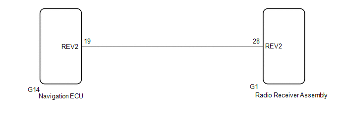
This circuit includes the navigation ECU and radio receiver assembly.
WIRING DIAGRAM
PROCEDURE
| 1. | CHECK HARNESS AND CONNECTOR (RADIO RECEIVER ASSEMBLY - NAVIGATION ECU) |
(a) Disconnect the G1 radio receiver assembly connector.
(b) Disconnect the G14 navigation ECU connector.
(c) Measure the resistance according to the value(s) in the table below.
Standard Resistance:
| Tester Connection | Condition | Specified Condition |
|---|---|---|
| G1-28 (REV2) - G14-19 (REV2) | Always | Below 1 Ω |
| G1-28 (REV2) or G14-19 (REV2) - Body ground | Always | 10 kΩ or higher |
| OK |  | PROCEED TO NEXT SUSPECTED AREA SHOWN IN PROBLEM SYMPTOMS TABLE |
.gif)
| NG | | REPAIR OR REPLACE HARNESS OR CONNECTOR |
READ NEXT:
 Route cannot be Calculated
PROCEDURE 1. SET DESTINATION (a) Set another destination and check if the system can calculate the route correctly. OK: Route can be correctly calculated. OK END NG PROCEED T
Satellite Radio Broadcast cannot be Received
CAUTION / NOTICE / HINT NOTICE: Some satellite radio broadcasts require payment. A contract must be made between a satellite radio company and the user. If the contract expires, it will not be possibl
Satellite Radio Broadcast cannot be Selected or After Selecting Broadcast, Broadcast cannot be Added into Memory
CAUTION / NOTICE / HINT NOTICE: Some satellite radio broadcasts require payment. A contract must be made between a satellite radio company and the user. If the contract expires, it will not be possibl
SEE MORE:
On-vehicle Inspection
ON-VEHICLE INSPECTION PROCEDURE 1. INSPECT STOP LIGHT SWITCH ASSEMBLY (a) Disconnect the A80 stop light switch assembly connector. *a Front view of wire harness connector (to Stop Light Switch Assembly) (b) Measure the voltage and resistance on the wire harness side connec
Installation
INSTALLATION CAUTION / NOTICE / HINT NOTICE:
Avoid any impact to the blind spot monitor sensor.
Do not drop the blind spot monitor sensor. If it is dropped, replace it with a new one.
HINT:
The blind spot monitor beam axis confirmation is performed to confirm whether the sensor beam axis
© 2016-2026 Copyright www.lexguide.net
