Lexus ES: Replacement
REPLACEMENT
PROCEDURE
1. REPLACE STRAIGHT PIN
NOTICE:
If a straight pin is deformed, replace it.
(a) Using a plastic hammer, tap in new straight pins to the cylinder block sub-assembly.
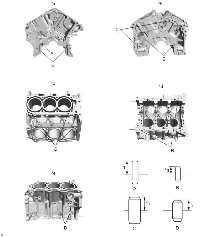
| *a | Front Side | *b | Rear Side |
| *c | Top Side | *d | Bottom Side |
| *e | RH Side | *f | 23 mm (0.906 in.) |
| *g | 6 mm (0.236 in.) | *h | 11 mm (0.433 in.) |
| *i | 9 mm (0.354 in.) | - | - |
Standard Protrusion Height:
| Item | Specified Condition |
|---|---|
| Pin (A) | 23 mm (0.906 in.) |
| Pin (B) | 6 mm (0.236 in.) |
| Pin (C) | 11 mm (0.433 in.) |
| Pin (D) | 9 mm (0.354 in.) |
2. REPLACE STUD BOLT
NOTICE:
If a stud bolt is deformed or its threads are damaged, replace it.
(a) Using E8 and E10 "TORX" socket wrenches, install the stud bolts to the cylinder block sub-assembly.
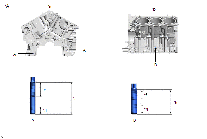
| *A | w/ Stud Bolt | - | - |
| *a | Front Side | *b | LH Side |
| *c | 24 mm (0.9449 in.) | *d | 12 mm (0.4724 in.) |
| *e | 52 mm (2.05 in.) | *f | 23 mm (0.906 in.) |
| *g | 15 mm (0.591 in.) | *h | 40 mm (1.57 in.) |
Torque:
10 N·m {102 kgf·cm, 7 ft·lbf}
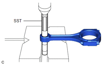
3. REPLACE CONNECTING ROD SMALL END BUSH
| (a) Using SST and a press, press out the connecting rod small end bush. SST: 09222-30010 |
|
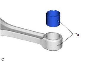
| (b) Align the oil hole of a new connecting rod small end bush with the oil hole of the connecting rod. |
|
| (c) Using SST and a press, push in the connecting rod small end bush. SST: 09222-30010 |
|
| (d) Using a pin hole grinder, hone the connecting rod small end bush to obtain the standard oil clearance between the connecting rod small end bush and piston pin. Standard Oil Clearance: 0.005 to 0.011 mm (0.000197 to 0.000433 in.) |
|
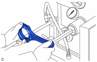
(e) Coat the piston pin with engine oil, and push it into the connecting rod with your thumb.
HINT:
Check that the piston pin fits at a normal room temperature.
READ NEXT:
 Reassembly
REASSEMBLY PROCEDURE 1. INSTALL NO. 1 OIL NOZZLE SUB-ASSEMBLY (a) Using a 5 mm hexagon socket wrench, install the 3 No. 1 oil nozzle sub-assemblies to the cylinder block sub-assembly with the 3 bol
Precaution
PRECAUTION HINT:
Any digits beyond the 1/100 mm (1/1000 in.) place for standard, minimum and maximum values should be used as a reference only.
When both standard and maximum or minimum values ar
SEE MORE:
Problem Symptoms Table
PROBLEM SYMPTOMS TABLE HINT:
Use the table below to help determine the cause of problem symptoms. If multiple suspected areas are listed, the potential causes of the symptoms are listed in order of probability in the "Suspected Area" column of the table. Check each symptom by checking the suspect
Water Pump
ComponentsCOMPONENTS ILLUSTRATION *1 ENGINE WATER PUMP ASSEMBLY (WATER INLET HOUSING) *2 GASKET *3 STUD BOLT - - N*m (kgf*cm, ft.*lbf): Specified torque ● Non-reusable part InstallationINSTALLATION CAUTION / NOTICE / HINT NOTICE: This procedure includes the inst
