Lexus ES: Removal
REMOVAL
CAUTION / NOTICE / HINT
The necessary procedures (adjustment, calibration, initialization, or registration) that must be performed after parts are removed and installed, or replaced during No. 2 clearance warning buzzer removal/installation are shown below.
Necessary Procedure After Parts Removed/Installed/Replaced (for HV Model)| Replaced Part or Performed Procedure | Necessary Procedures | Effect/Inoperative Function When Necessary Procedures are not Performed | Link |
|---|---|---|---|
|
*: When performing learning using the Techstream.
Click here | |||
| Disconnect cable from negative auxiliary battery terminal | Perform steering sensor zero point calibration | Lane Control System | |
| Pre-collision System | |||
| Parking Support Brake System* | |||
| Lighting System | |||
| Memorize steering angle neutral point | Parking Assist Monitor System | | |
| Panoramic View Monitor System | | ||
| Initialize power trunk lid system | Power Trunk Lid System | | |
CAUTION:
Some of these service operations affect the SRS airbag system. Read the precautionary notices concerning the SRS airbag system before servicing.
.png)
Click here .gif)
NOTICE:
- After the power switch is turned off, the radio receiver assembly records various types of memory and settings. As a result, after turning the power switch off, make sure to wait at least 85 seconds before disconnecting the cable from the negative (-) auxiliary battery terminal. (for Audio and Visual System)
- After the power switch is turned off, the radio receiver assembly records various types of memory and settings. As a result, after turning the power switch off, make sure to wait at least 85 seconds before disconnecting the cable from the negative (-) auxiliary battery terminal. (for Navigation System)
| Replaced Part or Performed Procedure | Necessary Procedures | Effect/Inoperative Function When Necessary Procedures are not Performed | Link |
|---|---|---|---|
|
*: When performing learning using the Techstream.
Click here | |||
| Disconnect cable from negative battery terminal | Perform steering sensor zero point calibration | Lane Control System | |
| Pre-collision System | |||
| Parking Support Brake System* | |||
| Lighting System | |||
| Memorize steering angle neutral point | Parking Assist Monitor System | | |
| Panoramic View Monitor System | | ||
| Initialize power trunk lid system | Power Trunk Lid System | | |
CAUTION:
Some of these service operations affect the SRS airbag system. Read the precautionary notices concerning the SRS airbag system before servicing.
Click here
NOTICE:
- After the engine switch is turned off, the radio receiver assembly records various types of memory and settings. As a result, after turning the engine switch off, make sure to wait at least 85 seconds before disconnecting the cable from the negative (-) battery terminal. (for Audio and Visual System)
- After the engine switch is turned off, the radio receiver assembly records various types of memory and settings. As a result, after turning the engine switch off, make sure to wait at least 85 seconds before disconnecting the cable from the negative (-) battery terminal. (for Navigation System)
PROCEDURE
1. REMOVE REAR SEAT ASSEMBLY
Click here
2. REMOVE REAR DOOR SCUFF PLATE LH (for HV Model)
Click here
3. REMOVE REAR DOOR SCUFF PLATE LH (for Gasoline Model)
Click here
4. REMOVE REAR DOOR SCUFF PLATE RH (for HV Model)
HINT:
Use the same procedure as for the LH side.
5. REMOVE REAR DOOR SCUFF PLATE RH (for Gasoline Model)
HINT:
Use the same procedure as for the LH side.
6. REMOVE REAR SEAT SIDE GARNISH LH
Click here
7. REMOVE REAR SEAT SIDE GARNISH RH
HINT:
Use the same procedure as for the LH side.
8. REMOVE ROOF SIDE INNER GARNISH ASSEMBLY LH
Click here
9. REMOVE ROOF SIDE INNER GARNISH ASSEMBLY RH
HINT:
Use the same procedure as for the LH side.
10. DISCONNECT REAR SEAT OUTER BELT ASSEMBLY LH
Click here
11. DISCONNECT REAR SEAT OUTER BELT ASSEMBLY RH
HINT:
Use the same procedure as for the LH side.
12. REMOVE CENTER STOP LIGHT SET (w/o Rear Sunshade)
Click here
13. REMOVE REAR SEAT SHOULDER BELT COVER
Click here
14. REMOVE PACKAGE TRAY TRIM PANEL ASSEMBLY (w/o Rear Sunshade)
Click here
15. REMOVE PACKAGE TRAY TRIM PANEL ASSEMBLY (w/ Rear Sunshade)
Click here
16. REMOVE NO. 2 CLEARANCE WARNING BUZZER
| (a) Disengage the clamp. |
|
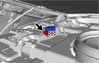
(b) Disconnect the connector to remove the No. 2 clearance warning buzzer.
READ NEXT:
 Components
COMPONENTS ILLUSTRATION *1 CLEARANCE WARNING ECU ASSEMBLY *2 ECU INTEGRATION BOX RH *3 GLOVE COMPARTMENT DOOR ASSEMBLY - -
Installation
INSTALLATION PROCEDURE 1. INSTALL CLEARANCE WARNING ECU ASSEMBLY (a) Engage the claw to install the clearance warning ECU assembly as shown in the illustration. Install in this Direction 2.
SEE MORE:
Parts Location
PARTS LOCATION ILLUSTRATION *1 HYBRID VEHICLE CONTROL ECU *2 REAR TELEVISION CAMERA ASSEMBLY *3 BLIND SPOT MONITOR SENSOR RH (w/ Blind Spot Monitor System) *4 BLIND SPOT MONITOR SENSOR LH (w/ Blind Spot Monitor System) ILLUSTRATION *1 MAIN BODY ECU (MULTIPLEX NETWORK BOD
Power Trunk Lid does not Operate Using Cabin Switch
DESCRIPTION The trunk and fuel switch assembly (luggage compartment door opening switch) signal is sent to the luggage closer motor assembly. If the power trunk lid does not operate using the trunk and fuel (luggage compartment door opening switch), a trunk and fuel (luggage compartment door opening
