Lexus ES: Parts Location
PARTS LOCATION
ILLUSTRATION
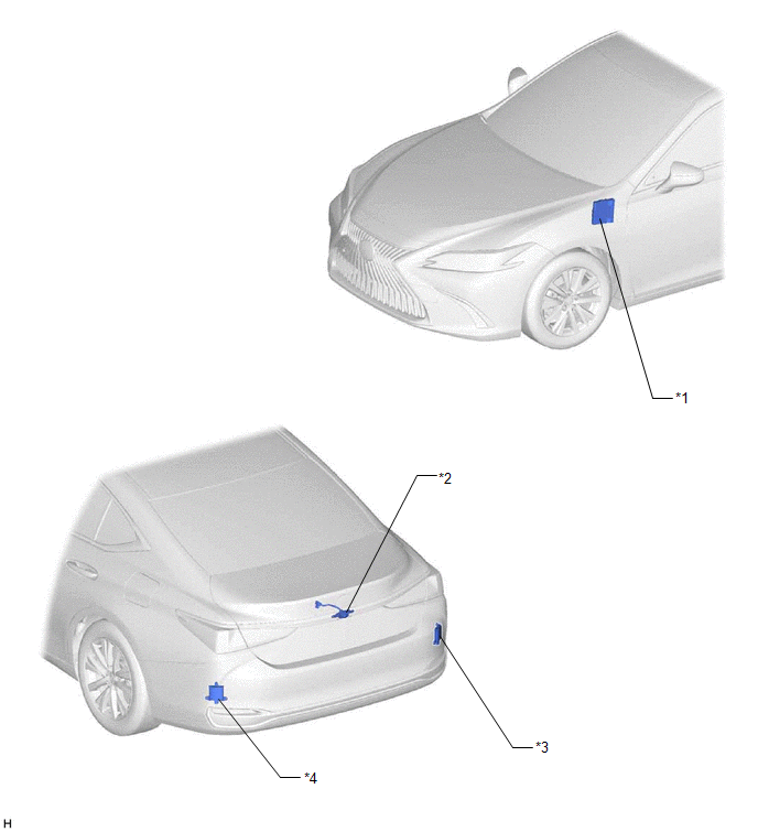
| *1 | HYBRID VEHICLE CONTROL ECU | *2 | REAR TELEVISION CAMERA ASSEMBLY |
| *3 | BLIND SPOT MONITOR SENSOR RH (w/ Blind Spot Monitor System) | *4 | BLIND SPOT MONITOR SENSOR LH (w/ Blind Spot Monitor System) |
ILLUSTRATION
.png)
| *1 | MAIN BODY ECU (MULTIPLEX NETWORK BODY ECU) | *2 | STEERING SENSOR |
| *3 | MULTI-DISPLAY ASSEMBLY | *4 | DLC3 |
| *5 | INSTRUMENT PANEL JUNCTION BLOCK ASSEMBLY - ECU-IG1 NO. 2 FUSE - ECU-DCC NO. 1 FUSE - IG1-NO. 1 RELAY - BKUP LP RELAY (for 8 inch display) | *6 | CLEARANCE WARNING ECU ASSEMBLY (w/ Parking Support Alert System) |
| *7 | RADIO RECEIVER ASSEMBLY | - | - |
READ NEXT:
 Precaution
PRECAUTION PRECAUTION FOR DISCONNECTING CABLE FROM NEGATIVE AUXILIARY BATTERY TERMINAL NOTICE: When disconnecting the cable from the negative (-) auxiliary battery terminal, initialize the following s
Problem Symptoms Table
PROBLEM SYMPTOMS TABLE NOTICE:
The following inspection procedures for the parking assist monitor system are based on the assumption that the audio and visual system*1 or navigation system*2 is nor
Reverse Signal Circuit
DESCRIPTION The multi-display receives a reverse signal from the BK UP LP relay*1 or clearance warning ECU assembly*2.
*1: w/o Parking Support Alert System
*2: w/ Parking Support Alert System
SEE MORE:
Disassembly
DISASSEMBLY CAUTION / NOTICE / HINT NOTICE: This procedure includes the removal of small-head bolts. Refer to Small-Head Bolts of Basic Repair Hint to identify the small-head bolts. Click here PROCEDURE 1. REMOVE SPARK PLUG Click here 2. REMOVE KNOCK CONTROL SENSOR Click here 3. REMOVE ENGINE
Generator Temperature Sensor Voltage Out of Range (P0A361C,P0A361F)
DTC SUMMARY MALFUNCTION DESCRIPTION These DTCs are stored when the generator temperature sensor output is abnormal. The cause of this malfunction may be one of the following: Generator temperature sensor malfunction
Internal generator temperature sensor malfunction
Open or short in generator te
© 2016-2026 Copyright www.lexguide.net
