Lexus ES: Removal
REMOVAL
CAUTION / NOTICE / HINT
The necessary procedures (adjustment, calibration, initialization, or registration) that must be performed after parts are removed and installed, or replaced during front bumper assembly removal/installation are shown below.
Necessary Procedure After Parts Removed/Installed/Replaced (for HV Model)| Replaced Part or Performed Procedure | Necessary Procedure | Effect/Inoperative Function when Necessary Procedure not Performed | Link |
|---|---|---|---|
| Front television camera view adjustment | Panoramic View Monitor System (for HV Model) | for Initialization for Calibration |
| Front bumper assembly |
|
| |
| Replaced Part or Performed Procedure | Necessary Procedure | Effect/Inoperative Function when Necessary Procedure not Performed | Link |
|---|---|---|---|
| Front television camera view adjustment | Panoramic View Monitor System (for Gasoline Model) | for Initialization for Calibration |
| Front bumper assembly |
|
| |
HINT:
When the front bumper is damaged or deformed due to an accident or contact with other objects, etc., or the bumper installation area on the body is repaired, it is necessary to perform millimeter wave radarsensor adjustment.
Click here .gif)
PROCEDURE
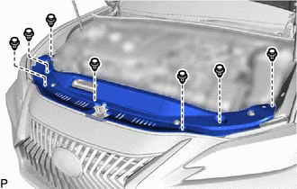
1. REMOVE COOL AIR INTAKE DUCT SEAL
| (a) Remove the 7 clips. |
|
(b) Disengage the guide and remove the cool air intake duct seal as shown in the illustration.
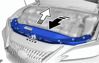
.png) | Remove in this Direction (1) |
.png) | Remove in this Direction (2) |
2. REMOVE FRONT BUMPER ASSEMBLY
(a) Apply protective tape around the front bumper assembly as shown in the illustration.
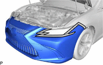
.png) | Protective Tape |
HINT:
Use the same procedure for the RH side and LH side.
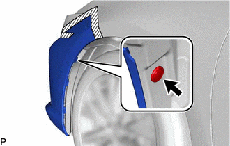
(b) Using a screwdriver with its tip wrapped with protective tape, disengage the 3 claws as shown in the illustration.
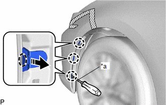
| *a | Protective Tape |
.png) | Insert Screwdriver Here |
| | Remove in this Direction |
HINT:
Use the same procedure for the RH side and LH side.
| (c) Remove the clip. HINT: Use the same procedure for the RH side and LH side. |
|
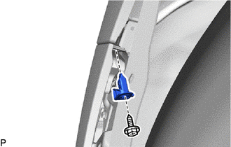
| (d) Remove the screw and front bumper side mounting bracket. HINT: Use the same procedure for the RH side and LH side. |
|
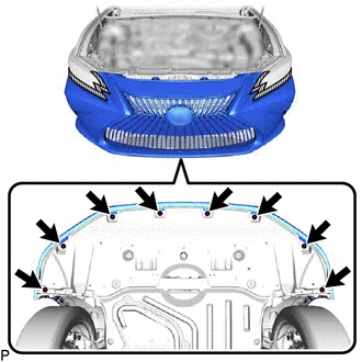
| (e) Remove the 8 screws. |
|
(f) Disengage the 7 claws and guide as shown in the illustration.
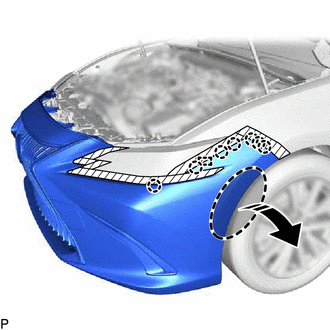
| | Place Hand Here |
| | Remove in this Direction |
HINT:
Use the same procedure for the RH side and LH side.
| (g) Disconnect the 2 connectors. |
|
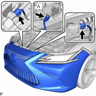
(h) w/ Pre-collision System:
(1) Disconnect the connector.
(i) Pull back the side of the front bumper assembly and disconnect the connector.
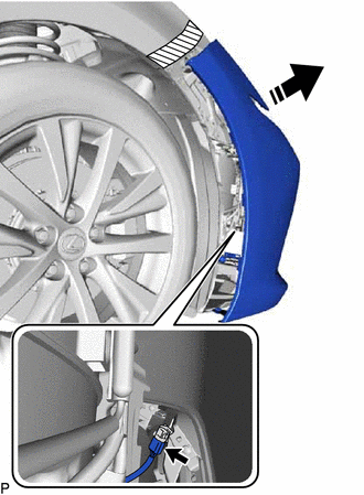
| | Remove in this Direction |
NOTICE:
Do not apply excessive force when pulling back the front bumper assembly.
| (j) Remove the 4 bolts. |
|
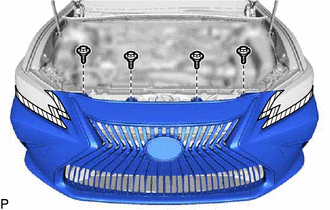
(k) Disengage the 4 claws and 4 guides to remove the front bumper assembly as shown in the illustration.
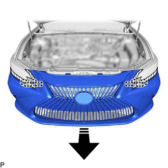
| | Remove in this Direction |
READ NEXT:
 Disassembly
DISASSEMBLY PROCEDURE 1. REMOVE FRONT BUMPER EXTENSION MOUNTING BRACKET (for Bar Type Radiator Grille) (a) Remove the 2 screws. (b) Disengage the 4 claws to remove the front bumper exte
Reassembly
REASSEMBLY PROCEDURE 1. INSTALL FRONT BUMPER SIDE SUPPORT LH (a) Engage the clip as shown in the illustration. Install in this Direction (b) Install the front bumper side support LH with
Installation
INSTALLATION CAUTION / NOTICE / HINT HINT: When the front bumper is damaged or deformed due to an accident or contact with other objects, etc., or if the bumper installation area of the vehicle body h
SEE MORE:
Operation Check
OPERATION CHECK INPUT SIGNAL CHECK (a) Connect the Techstream to the DLC3. (b) Check the steering pad switch assembly using the Data List function of the Techstream (cruise control main switch, -SET switch, +RES switch and CANCEL switch). Click here *1 Steering Pad Switch Assembly *a C
Inside Vehicle
INSIDE VEHICLE
These are maintenance and inspection items that are considered to be
the owner's responsibility.
The owner can do them or they can have them done at a service center.
These items include those that should be checked on a daily basis, those
that in most cases
