Lexus ES: Disassembly
DISASSEMBLY
PROCEDURE
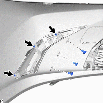
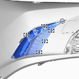
1. REMOVE FRONT BUMPER EXTENSION MOUNTING BRACKET (for Bar Type Radiator Grille)
| (a) Remove the 2 screws. |
|
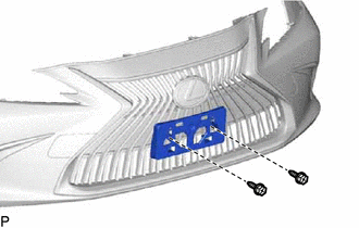
(b) Disengage the 4 claws to remove the front bumper extension mounting bracket as shown in the illustration.
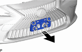
.png) | Remove in this Direction |
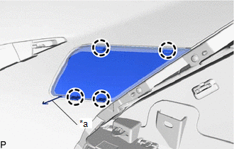
2. REMOVE FRONT BUMPER EXTENSION MOUNTING BRACKET (for Mesh Type Radiator Grille)
| (a) Remove the 2 screws. |
|
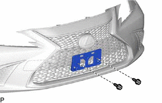
(b) Disengage the 2 claws to remove the front bumper extension mounting bracket as shown in the illustration.
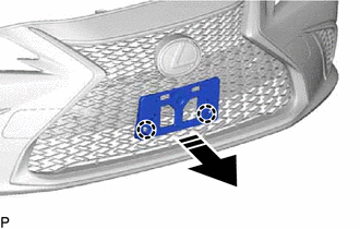
| | Remove in this Direction |
3. REMOVE SMOG VENTILATION SENSOR
Click here .gif)
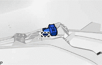
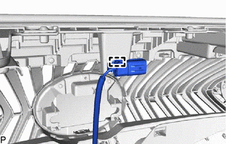
4. REMOVE WIRING HARNESS CONNECTOR (w/o Parking Support Alert System)
| (a) Disengage the clamp to remove the wiring harness connector. |
|
5. REMOVE FRONT CENTER ULTRASONIC SENSOR (w/ Parking Support Alert System)
Click here
HINT:
Use the same procedure for the RH side and LH side.
6. REMOVE FRONT CORNER ULTRASONIC SENSOR (w/ Parking Support Alert System)
Click here
HINT:
Use the same procedure for the RH side and LH side.
7. REMOVE FRONT CORNER ULTRASONIC SENSOR RETAINER (w/ Parking Support Alert System)
Click here
HINT:
Use the same procedure for the RH side and LH side.
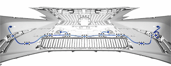
8. REMOVE NO. 4 ENGINE ROOM WIRE (w/ Parking Support Alert System)
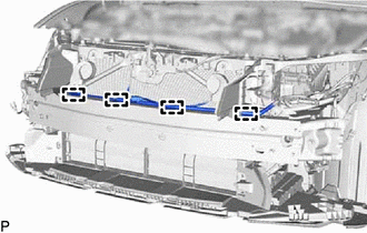
(a) Disengage the 10 clamps to remove the No. 4 engine room wire.
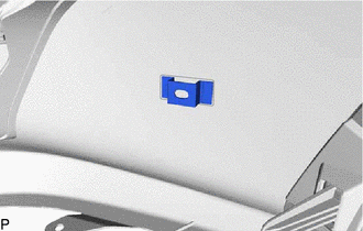
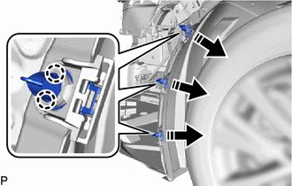
9. REMOVE ULTRASONIC SENSOR CLIP (w/ Parking Support Alert System)
| (a) Remove the ultrasonic sensor clip. HINT: Use the same procedure for the RH side and LH side. |
|
10. REMOVE MILLIMETER WAVE RADAR SENSOR ASSEMBLY (w/ Pre-collision System)
Click here
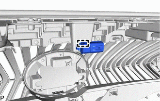
11. REMOVE WIRING HARNESS CONNECTOR (w/o Panoramic View Monitor System)
| (a) Disengage the clamp to remove the wiring harness connector. |
|
12. REMOVE FRONT TELEVISION CAMERA ASSEMBLY (w/ Panoramic View Monitor System)
Click here
13. REMOVE NO. 5 ENGINE ROOM WIRE (w/ Panoramic View Monitor System)
| (a) Disengage the clamp to remove the No. 5 engine room wire. |
|
14. REMOVE RADIATOR GRILLE GARNISH SUB-ASSEMBLY LH (for Bar Type Radiator Grille)
| (a) Remove the 3 screws. |
|
| (b) Disengage the 4 claws and 3 guides to remove the radiator grille garnish sub-assembly LH. |
|
15. REMOVE RADIATOR GRILLE GARNISH SUB-ASSEMBLY RH (for Bar Type Radiator Grille)
HINT:
Use the same procedure as for the LH side.
16. REMOVE FRONT BUMPER SIDE MOULDING LH (for Bar Type Radiator Grille)
| (a) Disengage the 4 claws and 3 guides to remove the front bumper side moulding LH. |
|
17. REMOVE FRONT BUMPER SIDE MOULDING RH (for Bar Type Radiator Grille)
HINT:
Use the same procedure as for the LH side.
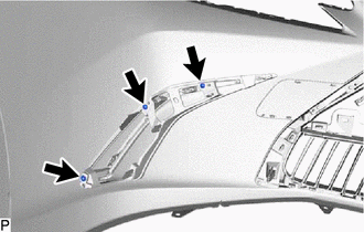
18. REMOVE RADIATOR GRILLE GARNISH SUB-ASSEMBLY LH (for Mesh Type Radiator Grille)
| (a) Remove the 3 screws and 3 outside moulding retainers. |
|
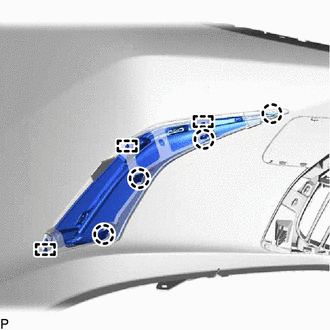
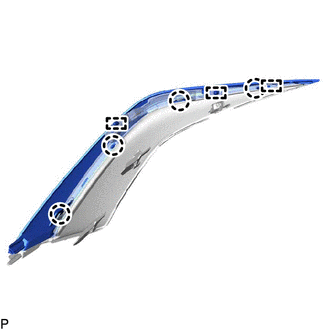
| (b) Disengage the claw and 5 guides to remove the radiator grille garnish sub-assembly LH. |
|
19. REMOVE RADIATOR GRILLE GARNISH SUB-ASSEMBLY RH (for Mesh Type Radiator Grille)
HINT:
Use the same procedure as for the LH side.
20. REMOVE FRONT BUMPER HOLE COVER LH (for TMC Made)
| (a) Disengage the 4 claws. |
|
(b) Disengage the hook to remove the front bumper hole cover LH.
21. REMOVE FRONT BUMPER HOLE COVER RH (for TMC Made)
HINT:
Use the same procedure as for the LH side.
22. REMOVE CENTER FRONT BUMPER SEAL
(a) Disengage the 5 clips.
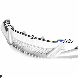
.png) | Double-sided Tape |
(b) Separate the double-sided tape and remove the center front bumper seal.
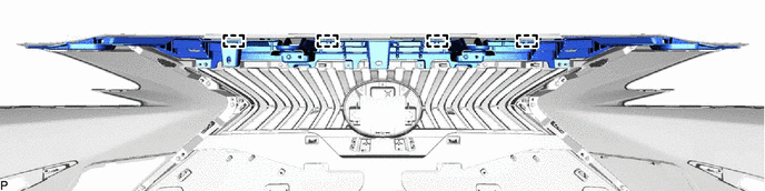
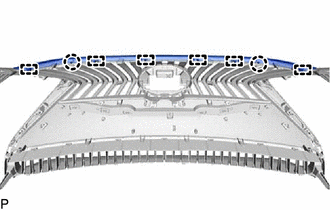
23. REMOVE UPPER RADIATOR GRILLE
(a) Remove the 8 screws.
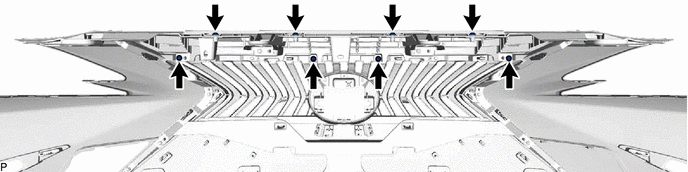
(b) Disengage the 4 guides and remove the upper radiator grille.
24. REMOVE UPPER FRONT BUMPER RETAINER
HINT:
Use the same procedure for the RH side and LH side.
| (a) Remove the screw. |
|
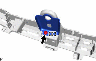
(b) Disengage the guide to remove the upper front bumper retainer.
25. REMOVE RADIATOR GRILLE (OR FRONT PANEL) EMBLEM
| (a) Remove the 2 screws. |
|
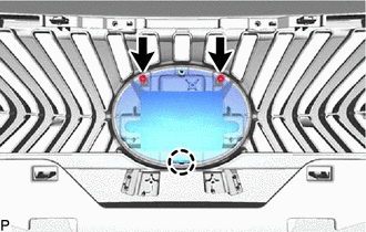
(b) Disengage the claw to remove the radiator grille (or front panel) emblem.
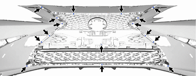
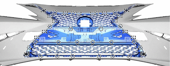
26. REMOVE RADIATOR GRILLE SUB-ASSEMBLY (for Bar Type Radiator Grille)
(a) Remove the 16 screws.
(b) Disengage the 22 claws and 16 guides to remove the outside radiator grille.
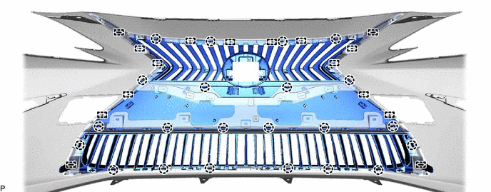
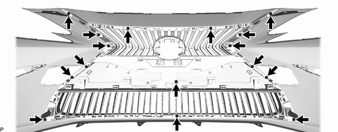
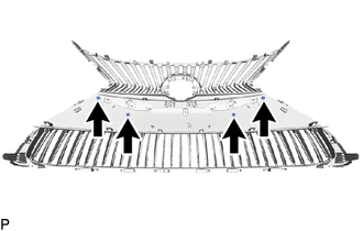
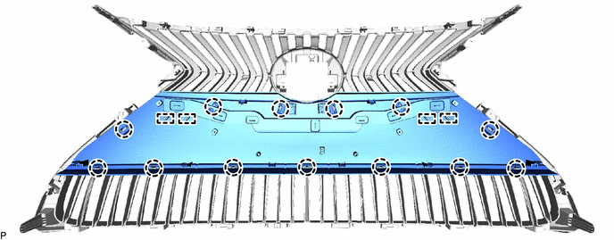
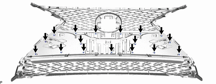
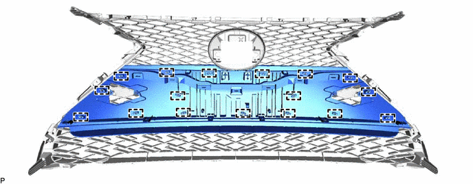
27. REMOVE RADIATOR GRILLE SUB-ASSEMBLY (for Mesh Type Radiator Grille)
(a) Remove the 16 screws.
(b) Disengage the 22 claws and 16 guides to remove the outside radiator grille.
28. REMOVE UPPER RADIATOR GRILLE MOULDING
| (a) Disengage the 2 claws and 6 guides to remove the upper radiator grille moulding. |
|
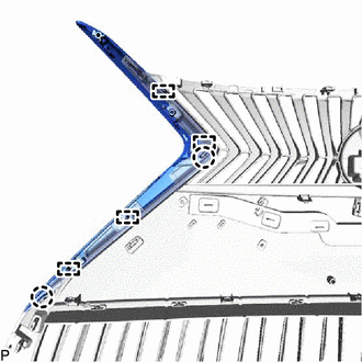
29. REMOVE RADIATOR GRILLE SIDE MOULDING LH
| (a) Disengage the 2 claws and 4 guides to remove the radiator grille side moulding LH. |
|
30. REMOVE RADIATOR GRILLE SIDE MOULDING RH
HINT:
Use the same procedure as for the LH side.
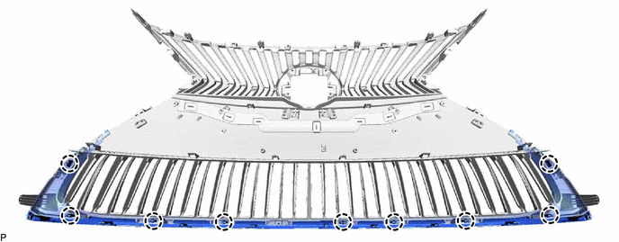
31. REMOVE LOWER RADIATOR GRILLE MOULDING
| (a) Remove the screw. |
|
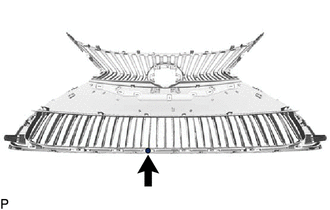
(b) Disengage the 9 claws to remove the lower radiator grille moulding.
32. REMOVE INSIDE RADIATOR GRILLE (for TMC Made)
(a) for Bar Type Radiator Grille:
| (1) Remove the 4 spring nuts. |
|
(2) Disengage the 13 claws and 4 guides to remove the inside radiator grille.
(b) for Mesh Type Radiator Grille:
(1) Remove the 17 spring nuts.
(2) Disengage the 17 guides to remove the inside radiator grille.
33. REMOVE PIN HOLD CLIP
(a) Disengage the 6 claws to remove the 3 pin hold clips as shown in the illustration.
| | Remove in this Direction |
HINT:
Use the same procedure for the RH side and LH side.
34. REMOVE FRONT FENDER LINER RETAINER
(a) Remove the 3 front fender liner retainers as shown in the illustration.
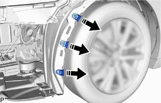
| | Remove in this Direction |
HINT:
Use the same procedure for the RH side and LH side.
35. REMOVE FRONT BUMPER ENERGY ABSORBER
(a) Remove the 4 clips.
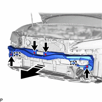
| | Remove in this Direction |
(b) Disengage the 2 guides to remove the front bumper energy absorber as shown in the illustration.
36. REMOVE NO. 2 FRONT BUMPER MOUNTING BRACKET
(a) Remove the 2 bolts.
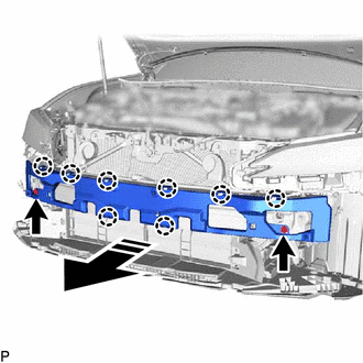
| | Remove in this Direction |
(b) Disengage the 8 claws to remove the No. 2 front bumper mounting bracket as shown in the illustration.
37. REMOVE FRONT BUMPER REINFORCEMENT SUB-ASSEMBLY
(a) Remove the headlight assembly LH.
Click here
(b) Remove the headlight assembly RH.
HINT:
Use the same procedure as for the LH side.
| (c) Disengage the 4 clamps. |
|
(d) Remove the 6 bolts and front bumper reinforcement sub-assembly as shown in the illustration.
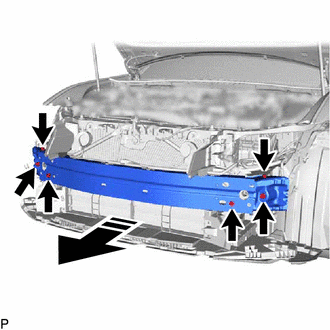
| | Remove in this Direction |
38. REMOVE FRONT BUMPER SIDE SUPPORT LH
| (a) Remove the bolt. |
|
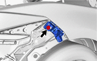
(b) Disengage the clip as shown in the illustration to remove the front bumper side support LH.
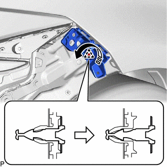
| | Remove in this Direction |
39. REMOVE FRONT BUMPER SIDE SUPPORT RH
HINT:
Use the same procedure as for the LH side.
READ NEXT:
 Reassembly
REASSEMBLY PROCEDURE 1. INSTALL FRONT BUMPER SIDE SUPPORT LH (a) Engage the clip as shown in the illustration. Install in this Direction (b) Install the front bumper side support LH with
Installation
INSTALLATION CAUTION / NOTICE / HINT HINT: When the front bumper is damaged or deformed due to an accident or contact with other objects, etc., or if the bumper installation area of the vehicle body h
SEE MORE:
How To Use This Manual
General Information
GENERAL INFORMATION
GENERAL DESCRIPTION
(a) This manual is written in accordance with SAE J2008.
(b) Repair operations can be separated mainly into the following 3 processes:
(1) Diagnosis
(2) Removing/Installing, Replacing, Disassembling/Reassembling, Checking and
Adju
Steering Angle Initialization Incomplete (C1694)
DESCRIPTION This DTC is stored when the rear television camera assembly judges that the maximum steering angle has not been memorized (steering angle setting is incomplete). DTC No. Detection Item DTC Detection Condition Trouble Area C1694 Steering Angle Initialization Incomplete Ma
