Lexus ES: Removal
REMOVAL
CAUTION / NOTICE / HINT
The necessary procedures (adjustment, calibration, initialization, or registration) that must be performed after parts are removed and installed, or replaced during kick door control sensor removal/installation are shown below.
Necessary Procedure After Parts Removed/Installed/Replaced (for Gasoline Model)| Replaced Part or Performed Procedure | Necessary Procedure | Effect/Inoperative Function When Necessary Procedures are not Performed | Link |
|---|---|---|---|
|
*: When performing learning using the Techstream.
Click here | |||
| Disconnect cable from negative battery terminal | Perform steering sensor zero point calibration | Lane Control System | |
| Pre-collision System | |||
| Parking Support Brake System* | |||
| Lighting System | |||
| Memorize steering angle neutral point | Parking Assist Monitor System | | |
| Panoramic View Monitor System | | ||
| Initialize power trunk lid system | Power Trunk Lid System | | |
| Rear bumper assembly (w/ Parking Support Brake System) |
|
| |
NOTICE:
- After the engine switch is turned off, the radio receiver assembly records various types of memory and settings. As a result, after turning the engine switch off, make sure to wait at least 85 seconds before disconnecting the cable from the negative (-) battery terminal. (for Audio and Visual System)
- After the engine switch is turned off, the radio receiver assembly records various types of memory and settings. As a result, after turning the engine switch off, make sure to wait at least 85 seconds before disconnecting the cable from the negative (-) battery terminal. (for Navigation System)
| Replaced Part or Performed Procedure | Necessary Procedure | Effect/Inoperative Function When Necessary Procedures are not Performed | Link |
|---|---|---|---|
|
*: When performing learning using the Techstream.
Click here | |||
| Disconnect cable from negative auxiliary battery terminal | Perform steering sensor zero point calibration | Lane Control System | |
| Pre-collision System | |||
| Parking Support Brake System* | |||
| Lighting System | |||
| Memorize steering angle neutral point | Parking Assist Monitor System | | |
| Panoramic View Monitor System | | ||
| Initialize power trunk lid system | Power Trunk Lid System | | |
| Rear bumper assembly (w/ Parking Support Brake System) |
|
| |
NOTICE:
- After the power switch is turned off, the radio receiver assembly records various types of memory and settings. As a result, after turning the power switch off, make sure to wait at least 85 seconds before disconnecting the cable from the negative (-) auxiliary battery terminal. (for Audio and Visual System)
- After the power switch is turned off, the radio receiver assembly records various types of memory and settings. As a result, after turning the power switch off, make sure to wait at least 85 seconds before disconnecting the cable from the negative (-) auxiliary battery terminal. (for Navigation System)
HINT:
If the rear bumper assembly is damaged, there is a possibility that the installation area of the blind spot monitor sensor may be deformed and the blind spot monitor system may not operate correctly. Visually inspect the blind spot monitor sensor installation area (vehicle body, stud bolts) to make sure it is not damaged.
Click here .gif)
If damage is found in the visual inspection, check the installation condition of the blind spot monitor sensor, and adjust the installation position of the blind spot monitor sensor as necessary.
PROCEDURE
1. PRECAUTION
NOTICE:
After turning the engine switch (for Gasoline Model) or power switch (for HV Model) off, waiting time may be required before disconnecting the cable from the negative (-) auxiliary battery terminal. Therefore, make sure to read the disconnecting the cable from the negative (-) auxiliary battery terminal notices before proceeding with work.
2. DISCONNECT CABLE FROM NEGATIVE AUXILIARY BATTERY TERMINAL
for 2GR-FKS:
Click here
for A25A-FXS:
Click here
3. REMOVE REAR BUMPER ASSEMBLY (for Single Type)
Click here
4. REMOVE REAR BUMPER ASSEMBLY (for Dual Type)
Click here
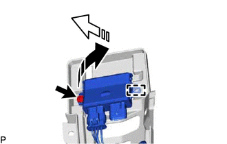
5. REMOVE KICK DOOR CONTROL SENSOR WITH BRACKET (except 2GR-FKS)
| (a) Disconnect the connector. NOTICE: Do not touch the terminals of the kick door control sensor connector. |
|
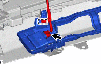
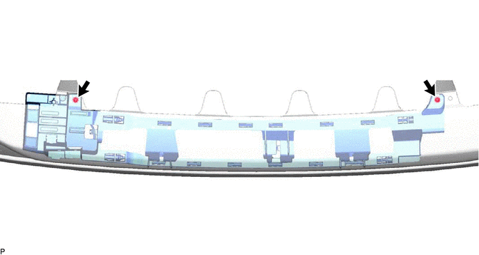
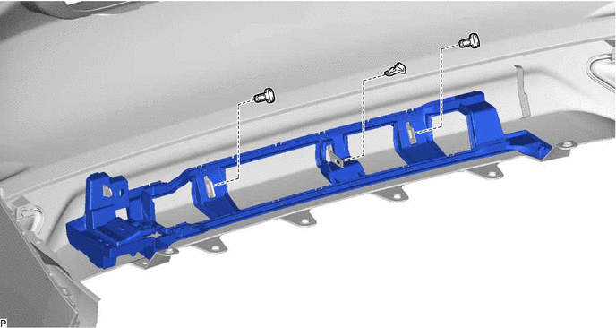
(b) Disengage the clamp.
(c) Remove the 2 clips.
(d) Remove the 3 screws.
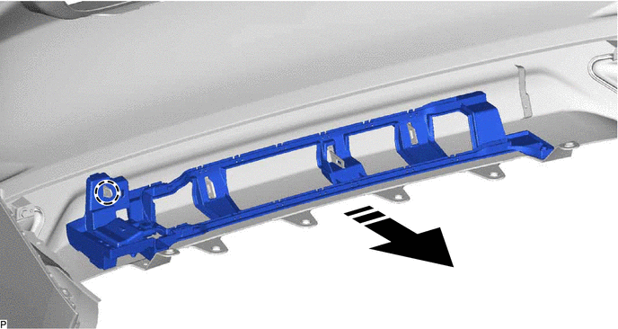
(e) Disengage the claw to remove the kick door control sensor with bracket as shown in the illustration.
.png) | Remove in this Direction | - | - |
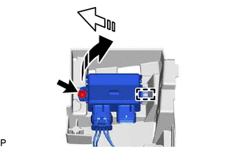
6. REMOVE KICK DOOR CONTROL SENSOR WITH BRACKET (for 2GR-FKS)
| (a) Disconnect the connector. NOTICE: Do not touch the terminals of the kick door control sensor connector. |
|
(b) Disengage the clamp.
(c) Remove the 2 screws.
(d) Remove the 3 clips.
(e) Disengage the claw to remove the kick door control sensor with bracket as shown in the illustration.
| | Remove in this Direction | - | - |
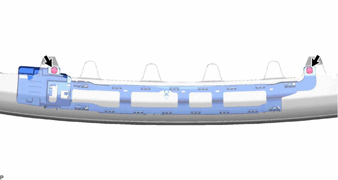
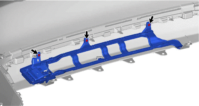
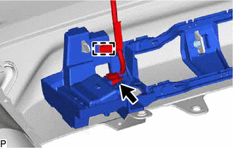
7. REMOVE KICK DOOR CONTROL SENSOR (except 2GR-FKS)
(a) Disengage the 16 claws.
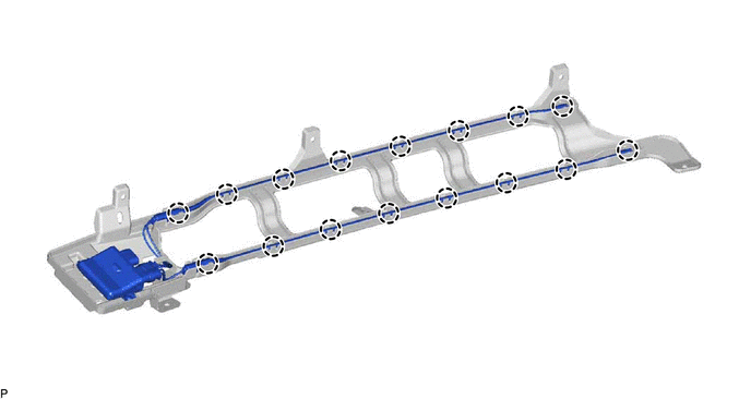
(b) Remove the screw.
| | Remove in this Direction (1) |
.png) | Remove in this Direction (2) |
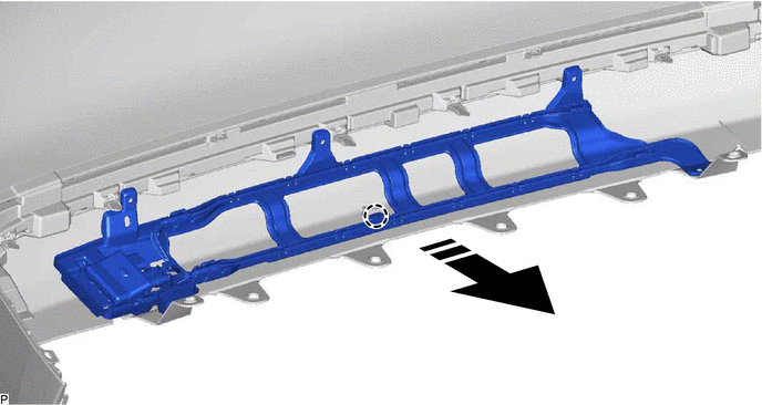
(c) Disengage the guide to remove the kick door control sensor from the kick door control bracket as shown in the illustration.
NOTICE:
- Do not subject the kick door control sensor to a strong impact or drop it.
- Do not reuse a kick door control sensor which has been subjected to a strong impact or dropped.
- Be careful not to pull the wire harness.
- Be careful not to twist the wire harness.
8. REMOVE KICK DOOR CONTROL SENSOR (for 2GR-FKS)
(a) Disengage the 16 claws.
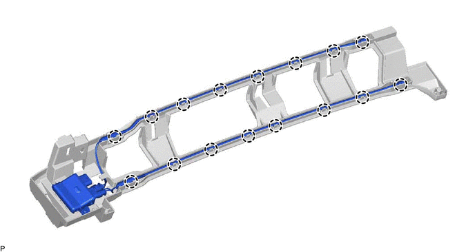
(b) Remove the screw.
| | Remove in this Direction (1) |
| | Remove in this Direction (2) |
(c) Disengage the guide to remove the kick door control sensor from the kick door control bracket as shown in the illustration.
NOTICE:
- Do not subject the kick door control sensor to a strong impact or drop it.
- Do not reuse a kick door control sensor which has been subjected to a strong impact or dropped.
- Be careful not to pull the wire harness.
- Be careful not to twist the wire harness.
READ NEXT:
 Installation
INSTALLATION PROCEDURE 1. PRECAUTION NOTICE: After turning the engine switch (for Gasoline Model) or power switch (for HV Model) off, waiting time may be required before disconnecting the cable from t
Components
COMPONENTS ILLUSTRATION *A w/ Power Trunk Lid System - - *1 LUGGAGE COMPARTMENT DOOR ASSIST GRIP *2 LUGGAGE COMPARTMENT DOOR COVER *3 LUGGAGE LOCK CONTROL CABLE PLATE *4
SEE MORE:
Removal
REMOVAL CAUTION / NOTICE / HINT The necessary procedures (adjustment, calibration, initialization or registration) that must be performed after parts are removed and installed, or replaced during windshield glass sub-assembly removal/installation are shown below. Necessary Procedure After Parts Remo
Pressure Control Solenoid "G" Circuit Short to Battery (P280712)
DESCRIPTION Changing gears is performed by the ECM turning the solenoid (SL1, SL2, SL3, SL4, SL5 and SL6) valves on and off. If an open or short occurs in any of the solenoid valve circuits, the ECM controls the remaining normal solenoid valves to allow the vehicle to be driven. If all of the soleno
