Lexus ES: Installation
INSTALLATION
PROCEDURE
1. PRECAUTION
NOTICE:
After turning the engine switch (for Gasoline Model) or power switch (for HV Model) off, waiting time may be required before disconnecting the cable from the negative (-) auxiliary battery terminal. Therefore, make sure to read the disconnecting the cable from the negative (-) auxiliary battery terminal notices before proceeding with work.
2. INSTALL KICK DOOR CONTROL SENSOR (except 2GR-FKS)
(a) Engage the guide as shown in the illustration.
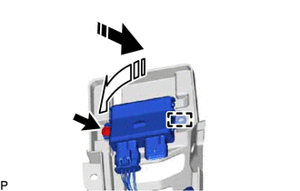
.png) | Install in this Direction (1) |
.png) | Install in this Direction (2) |
NOTICE:
- Do not subject the kick door control sensor to a strong impact or drop it.
- Do not reuse a kick door control sensor which has been subjected to a strong impact or dropped.
- Be careful not to pull the wire harness.
- Be careful not to twist the wire harness.
(b) Install the screw.
(c) Engage the 16 claws with each marking on the kick door control sensor facing up to install the kick door control sensor as shown in the illustration.
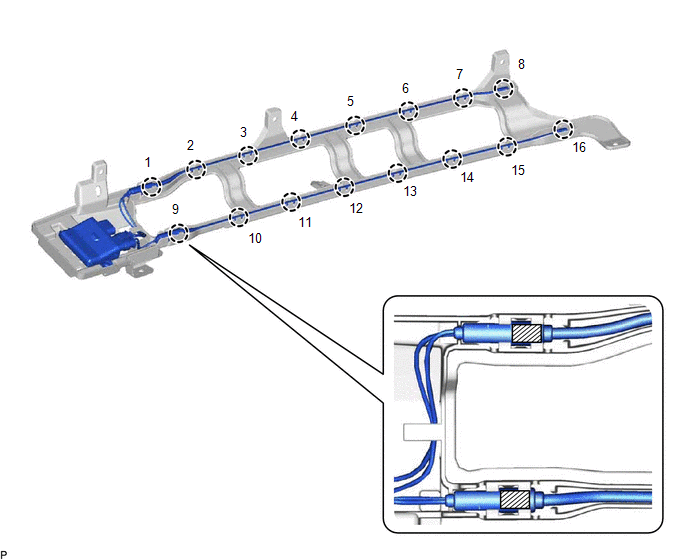
.png) | Marking (White) | - | - |
NOTICE:
Fully insert the kick door control sensor into the kick door control bracket.
HINT:
Engage each claw in the order shown in the illustration.
3. INSTALL KICK DOOR CONTROL SENSOR (for 2GR-FKS)
(a) Engage the guide to install the kick door control sensor as shown in the illustration.
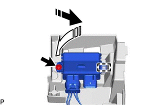
| | Install in this Direction (1) |
| | Install in this Direction (2) |
NOTICE:
- Do not subject the kick door control sensor to a strong impact or drop it.
- Do not reuse a kick door control sensor which has been subjected to a strong impact or dropped.
- Be careful not to pull the wire harness.
- Be careful not to twist the wire harness.
(b) Install the screw.
(c) Engage the 16 claws with each marking on the kick door control sensor facing up to install the kick door control sensor as shown in the illustration.
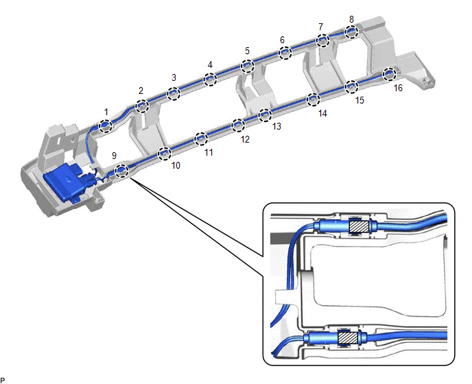
| | Marking (White) | - | - |
NOTICE:
Fully insert the kick door control sensor into the kick door control bracket.
HINT:
Engage each claw in the order shown in the illustration.
4. INSTALL KICK DOOR CONTROL SENSOR WITH BRACKET (except 2GR-FKS)
(a) Engage the claw as shown in the illustration.
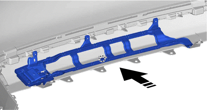
| | Install in this Direction | - | - |
(b) Install the 3 screws.
(c) Install the kick door control sensor with bracket with the 2 clips.
(d) Engage the clamp.
(e) Connect the connector.
NOTICE:
Do not touch the terminals of the kick door control sensor connector.
5. INSTALL KICK DOOR CONTROL SENSOR WITH BRACKET (for 2GR-FKS)
(a) Engage the claw as shown in the illustration.
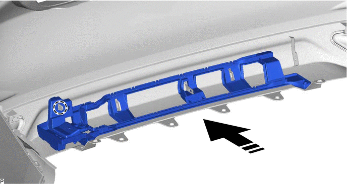
| | Install in this Direction | - | - |
(b) Install the 3 clips.
(c) Install the kick door control sensor with bracket with the 2 screws.
(d) Engage the clamp.
(e) Connect the connector.
NOTICE:
Do not touch the terminals of the kick door control sensor connector.
6. INSTALL REAR BUMPER ASSEMBLY (for Single Type)
Click here .gif)
7. INSTALL REAR BUMPER ASSEMBLY (for Dual Type)
Click here
8. CONNECT CABLE TO NEGATIVE AUXILIARY BATTERY TERMINAL
for 2GR-FKS:
Click here
for A25A-FXS:
Click here
9. INITIALIZE KICK DOOR CONTROL SENSOR
for Gasoline Model:
Click here
for HV Model:
Click here
10. INSPECT KICK DOOR CONTROL SENSOR
for Gasoline Model:
Click here
for HV Model:
Click here
READ NEXT:
 Components
COMPONENTS ILLUSTRATION *A w/ Power Trunk Lid System - - *1 LUGGAGE COMPARTMENT DOOR ASSIST GRIP *2 LUGGAGE COMPARTMENT DOOR COVER *3 LUGGAGE LOCK CONTROL CABLE PLATE *4
Disassembly
DISASSEMBLY CAUTION / NOTICE / HINT The necessary procedures (adjustment, calibration, initialization, or registration) that must be performed after parts are removed and installed, or replaced during
SEE MORE:
Utility
UTILITY ALL READINESS HINT:
With "All Readiness", you can check whether or not the DTC judgment has been completed by using the Techstream.
Check "All Readiness" after simulating malfunction symptoms or for validation after finishing repairs.
(a) Connect the Techstream to the DLC3. (b) Turn
Removal
REMOVAL PROCEDURE 1. REMOVE FRONT WHEEL LH Click here 2. REMOVE FRONT WHEEL OPENING EXTENSION PAD LH HINT: Use the same procedure as for the RH side. Click here 3. REMOVE REAR FENDER SPLASH SHIELD SUB-ASSEMBLY LH HINT: Use the same procedure as for the RH side. Click here 4. REMOVE PIN HOLD CL
