Lexus ES: Removal
REMOVAL
CAUTION / NOTICE / HINT
The necessary procedures (adjustment, calibration, initialization, or registration) that must be performed after parts are removed and installed, or replaced during motor generator control ECU kit removal/installation are shown below.
Necessary Procedures After Parts Removed/Installed/Replaced| Replaced Part or Performed Procedure | Necessary Procedure | Effect/Inoperative Function when Necessary Procedure not Performed | Link |
|---|---|---|---|
|
*: When performing learning using the Techstream.
Click here | |||
| Auxiliary battery terminal is disconnected/reconnected | Perform steering sensor zero point calibration | Lane Control System | |
| Pre-collision system | |||
| Parking Support Brake System* | |||
| Lighting system | |||
| Memorize steering angle neutral point | Parking assist monitor system | | |
| Panoramic view monitor system | | ||
| Initialize power trunk lid system | Power Trunk Lid System | | |
| Replacement of inverter with converter assembly | Resolver learning |
| |
| Replacement of ECM | Perform Vehicle Identification Number (VIN) registration | MIL illuminates | |
CAUTION:
-
Orange wire harnesses and connectors indicate high-voltage circuits. To prevent electric shock, always follow the procedure described in the repair manual.
.png)
Click here
.gif)
-
To prevent electric shock, wear insulated gloves when working on wire harnesses and components of the high voltage system.
.png)
NOTICE:
- After the power switch is turned off, the radio receiver assembly records various types of memory and settings. As a result, after turning the power switch off, make sure to wait at least 85 seconds before disconnecting the cable from the negative (-) auxiliary battery terminal. (for Audio and Visual System)
- After the power switch is turned off, the radio receiver assembly records various types of memory and settings. As a result, after turning the power switch off, make sure to wait at least 85 seconds before disconnecting the cable from the negative (-) auxiliary battery terminal. (for Navigation System)
-
If metal shavings are created when bolts are removed from the inverter with converter assembly, remove them using tape or equivalent.
.png)
- Use non-residue type tape.
PROCEDURE
1. REMOVE INVERTER WITH CONVERTER ASSEMBLY
Click here
2. REMOVE WIRE HARNESS CLAMP BRACKET
Click here
3. REMOVE INVERTER PROTECTOR
Click here
4. VERIFY THAT VOLTAGE OF INVERTER WITH CONVERTER IS 0 V
CAUTION:
Wear insulating gloves.
NOTICE:
Do not allow any foreign matter or water to enter the inverter with converter assembly.
| (a) Remove the protective tape from the HV floor under wire opening. |
|
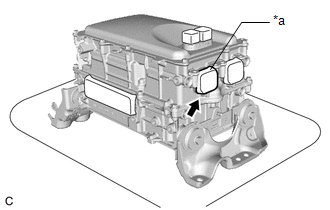
| (b) Using a voltmeter, measure the voltage between the high voltage cable connector terminals. Standard voltage: 0V HINT:
|
|
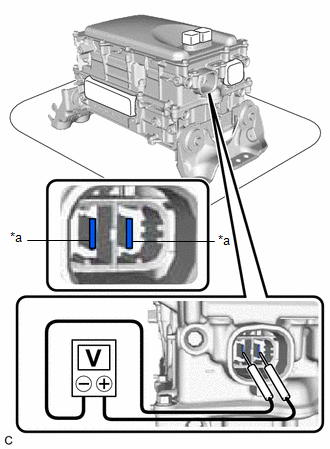
(c) Apply protective tape to the area that was exposed.
NOTICE:
Use non-residue type tape.
5. CLEAN INVERTER WITH CONVERTER ASSEMBLY
(a) Using a piece of cloth, clean the outside of the inverter with converter assembly and around the bolts.
NOTICE:
To prevent foreign matter from entering the inverter with converter assembly, make sure that the protective tape is not partially removed.
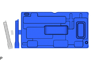
6. HOW TO PREVENT STATIC ELECTRICITY
SST: 09890-47010
NOTICE:
- Static electricity should be eliminated when removing/installing the inverter with converter assembly.
- Do not touch the electronic components of a circuit board.
- Keep clothes away from electronic components.
- Place the inverter with converter assembly and any removed electronic components on SST (antistatic mat).
| (a) Wear an antistatic wrist strap. |
|
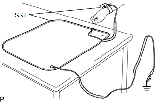
(b) Connect the ground clip of the antistatic mat securely to a ground point provided in the workshop or on a workbench (anchor bolt).
HINT:
If the ground clip cable is too short, use an extension cable.
(c) Connect the ground clip of the antistatic wrist strap securely to the specified point of the antistatic mat.
(d) When handling internal components of the inverter with converter assembly, use only antistatic gloves or bare hands to prevent damage from static electricity or the entry of foreign matter.
7. REMOVE INVERTER UPPER COVER
| (a) Remove the 10 bolts. |
|
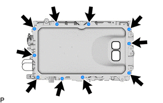
(b) Using a screwdriver with its tip wrapped with protective tape, remove the inverter upper cover from the inverter with converter assembly.
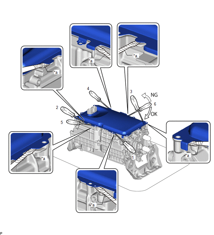
| *a | Protective Tape | - | - |
(c) Using a screwdriver with its tip wrapped with protective tape, remove the inverter upper cover from the inverter with converter assembly.
NOTICE:
-
Do not damage the sealing surfaces of the inverter with converter assembly.
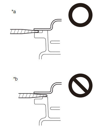
*a
OK
*b
NG
- Do not touch or allow grease or oil to contact the sealing surfaces of the inverter with converter assembly.
- Be careful not to damage the sealing surfaces of the inverter with converter assembly.
- To prevent internal components of the inverter with converter assembly from being damaged, do not insert the screwdriver excessively.
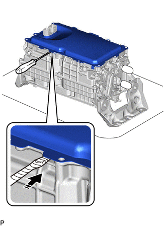
HINT:
I f the upper inverter panel is difficult to remove, place a screwdriver in a gap under the upper inverter cover and remove.
8. REMOVE SEAL PACKING FROM INVERTER WITH CONVERTER ASSEMBLY
NOTICE:
- Do not allow any removed seal packing to enter the inverter with converter assembly.
- Do not touch the circuit board.
- Do not allow any moisture to come into contact.
(a) Using a finger, remove any seal packing that has seeped into the inverter with converter assembly.
HINT:
Make sure to remove any seal packing which has seeped toward the inside of inverter with converter assembly before installing the seal packing removal cover, otherwise the seal packing may be pushed into the inverter with converter assembly.
| (b) Break off the seal packing removal cover and scraper at each break off line. |
|
(c) Set the seal packing removal cover on the inverter with converter assembly and secure it by lightly pressing it at the 2 areas shown in the illustration.
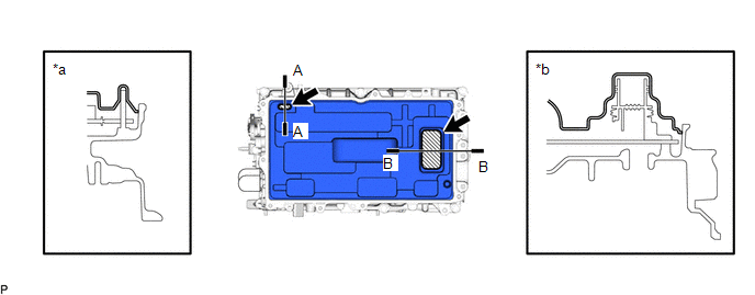
| *a | A-A Cross Section | *b | B-B Cross Section |
.png) | Push | - | - |
NOTICE:
Make sure that the seal packing removal cover is in secure contact with the inside surface of the inverter with converter assembly without any gaps.
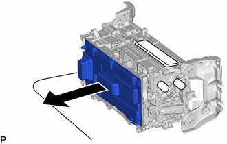
| (d) Place the inverter with converter assembly on its side on an antistatic mat as shown in the illustration. NOTICE:
|
|

(e) Using a scraper, remove any remaining seal packing from the inverter with converter assembly.
NOTICE:
-
It is not necessary to remove small amounts of seal packing which are not easily scraped off.
.png)
*a
Correct
*b
Incorrect
*c
Width of Sealing Surface
*d
Difficult to Remove Seal Packing
*e
Peeled Off Seal Packing
*f
Seal Packing Remaining on Full Width of Sealing Surface
-
Make sure to use the scraper supplied with the seal packing removal cover.
.png)
HINT:
Use the small end of the scraper to remove seal packing from small areas such as bolt holes.
(f) Using a clean piece of cloth, clean the sealing surfaces of the inverter with converter assembly.
NOTICE:
- Do not use compressed air or a vacuum cleaner to clean the sealing surfaces of the inverter with converter assembly.
- Do not use non-residue solvent to clean the sealing surfaces of the inverter with converter assembly.
| (g) Remove the seal packing removal cover. NOTICE: Make sure that the inverter with converter assembly is oriented correctly, otherwise seal packing may enter the inverter with converter assembly when removing the seal packing removal cover. |
|
(h) Check for and remove any foreign matter which has entered the inverter with converter assembly.
(i) Set the inverter with converter assembly upright.
(j) Clean the seal packing removal cover.
HINT:
As the seal packing removal cover will be reused, it is necessary to clean it to prevent foreign matter from entering the inverter with converter assembly and prevent damage.
9. REMOVE MOTOR GENERATOR CONTROL ECU KIT
CAUTION:
To prevent foreign matter from entering the inverter with converter assembly, once the seal packing removal cover has been removed, work cannot be suspended until the motor generator control ECU kit is reinstalled.
NOTICE:
- Do not touch the circuit board.
- Do not allow any foreign matter or water to enter the inverter with converter assembly.
(a) Install the seal packing removal cover to the inverter with converter assembly.
HINT:
The seal packing removal cover is installed to help prevent the motor generator control computer kit from being damaged if a part or tool is dropped on it.
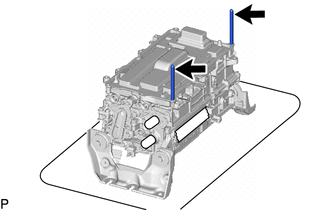
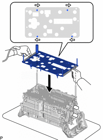
| (b) Install the 2 guide pins by hand at the positions shown in the illustration. NOTICE: Make sure that the guide pins are tightened securely. |
|
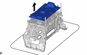
| (c) Remove the seal packing removal cover. |
|
(d) Check that the 4 screws of the circuit board replacement jig are unlocked, and then while holding the circuit board replacement jig by the ribs, align it with the guide pins and set it on the inverter with converter assembly.
HINT:
Make sure that circuit board replacement jig is perfectly level with the sealing surface.
.png) | Unlock |
.png) | Rib |
(e) Secure the circuit board replacement jig with the 2 bolts supplied with the circuit board replacement jig.
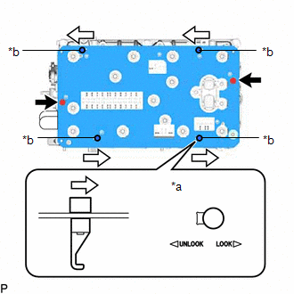
| *a | Locked |
| *b | Knob |
.png) | Bolt |
| | Lock |
NOTICE:
Tighten the bolt by hand until the head contacts the jig.
(f) Lock the 4 screws as shown in the illustration to secure the circuit board replacement jig to the circuit board.
NOTICE:
When locking the screws of the circuit board replacement jig, do not apply excessive force to the screws, otherwise the circuit board replacement jig may be damaged.
HINT:
Make sure that the screws of the circuit board replacement jig are securely locked.
(g) Turn the 4 knobs of the circuit board replacement jig clockwise and secure the 4 screws of the circuit board replacement jig.
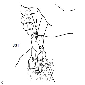
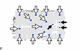
(h) Using SST, release the lock of each vibration dampening connector and raise the 28 vibration dampening connectors until they reach the stopper of the circuit board replacement jig.
SST: 09905-00040
NOTICE:
When disconnecting the vibration dampening connectors, release the lock of each connector with SST and then carefully lift the connector the specified amount.
HINT:
- To prevent the vibration dampening connectors from being pulled up excessively, use both hands to raise them slowly as shown in the illustration.
- The position of the lock will vary depending on the position of the vibration dampening connector. Refer to the arrows on the circuit board replacement jig.
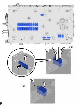
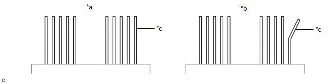
| *a | Connected Vibration Dampening Connector |
| *b | Disconnected Vibration Dampening Connector |
| *c | Stopper of The Circuit Board Replacement Jig |
(i) Using the screwdriver supplied with the circuit board replacement jig, remove the 3 bolts (A).
HINT:
If the bolts are difficult to remove from the circuit board replacement jig, use a magnet hand.
| | Bolt (A) |
| | Bolt (B) |
(j) Using the screwdriver supplied with the circuit board replacement jig, remove the 13 bolts (B).
HINT:
If the bolts are difficult to remove from the circuit board replacement jig, use a magnet hand.
(k) Remove the 2 inverter upper cover installation bolts.
(l) While holding the circuit board replacement jig by the ribs, evenly lift the circuit board replacement jig and circuit board straight up and remove it.
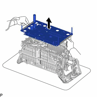
| | Rib |
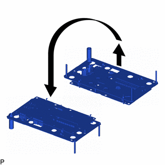
| (m) Place the circuit board replacement jig upside down on a clean workbench. |
|
(n) Check that the terminals of the inverter with converter assembly are not bent or damaged and that it is free of foreign matter.
| *a | Correct | *b | Incorrect |
| *c | Terminal | - | - |
NOTICE:
- Do not touch the terminals.
- If any of the terminals are bent, replace the inverter with converter assembly with a new one. Do not attempt to repair the terminals.
(o) Turn the 4 knobs of the circuit board replacement jig counterclockwise and release the 4 screws of the circuit board replacement jig.
| *a | Hold here | *b | Do not hold here |
| *c | Circuit Board | *d | Circuit Board Replacement Jig |
| *e | Knob | - | - |
| | Unlock | - | - |
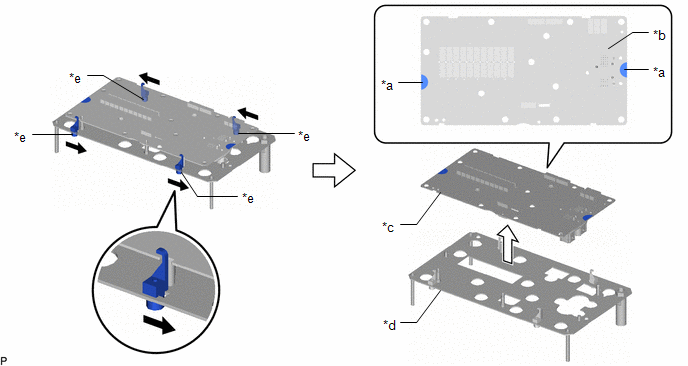
(p) Unlock the 4 circuit board replacement jig screws, and then while holding the sides of the circuit board or the top and bottom of the circuit board at the areas shown in the illustration, lift the circuit board to remove it from the circuit board replacement jig.
NOTICE:
Be careful not to touch any part of the circuit board other than the specified areas.
READ NEXT:
 Installation
INSTALLATION CAUTION / NOTICE / HINT CAUTION: To prevent foreign matter from entering the inverter with converter assembly, once the seal packing removal cover has been removed, work cannot be suspend
Precaution
PRECAUTION PRECAUTIONS FOR INSPECTING HYBRID CONTROL SYSTEM (a) Before the following operations are conducted, take precautions to prevent electric shock by turning the power switch off, wearing insul
SEE MORE:
Dtc Check / Clear
DTC CHECK / CLEAR CHECK FOR DTC (a) Connect the Techstream to the DLC3. (b) Turn the engine switch on (IG). (c) Turn the Techstream on. (d) Enter the following menus: Body Electrical / (desired system) / Trouble Codes. Body Electrical > Wiper > Trouble Codes Body Electrical > Main Body >
Parts Location
PARTS LOCATION ILLUSTRATION *1 ROOF ANTENNA ASSEMBLY - GPS - Telephone Main *2 CERTIFICATION ECU (SMART KEY ECU ASSEMBLY) *3 NAVIGATION ANTENNA ASSEMBLY - Telephone Sub *4 MAIN BODY ECU (MULTIPLEX NETWORK BODY ECU) *5 INSTRUMENT PANEL JUNCTION BLOCK ASSEMBLY - DCM FUSE - EC
