Lexus ES: Removal
REMOVAL
CAUTION / NOTICE / HINT
The necessary procedures (adjustment, calibration, initialization, or registration) that must be performed after parts are replaced during millimeter wave radar sensor assembly removal/installation are shown below.
Necessary Procedure After Parts Removed/Installed/Replaced (for Gasoline Model)| Replaced Part or Performed Procedure | Necessary Procedure | Effect/Inoperative Function when Necessary Procedure not Performed | Link |
|---|---|---|---|
| Millimeter wave radar sensor assembly | Adjust millimeter wave radar sensor assembly |
| |
| Replaced Part or Performed Procedure | Necessary Procedure | Effect/Inoperative Function when Necessary Procedure not Performed | Link |
|---|---|---|---|
| Millimeter wave radar sensor assembly | Adjust millimeter wave radar sensor assembly |
| |
PROCEDURE
1. REMOVE COOL AIR INTAKE DUCT SEAL
Click here .gif)
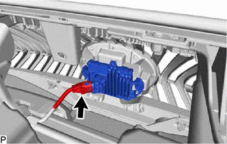
2. REMOVE MILLIMETER WAVE RADAR SENSOR ASSEMBLY
| (a) Disconnect the connector. |
|
(b) Remove the 2 bolts and screw.
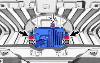
.png) | Bolt |
.png) | Screw |
(c) Disengage the 2 guides and remove the millimeter wave radar sensor assembly.
NOTICE:
Do not reuse the millimeter wave radar sensor assembly if it has been dropped or subjected to a severe impact.
READ NEXT:
 Adjustment
ADJUSTMENT CAUTION / NOTICE / HINT CAUTION: Radiofrequency radiation exposure information:
This equipment complies with FCC radiation exposure limits set forth for an uncontrolled environment.
Th
Installation
INSTALLATION PROCEDURE 1. INSTALL MILLIMETER WAVE RADAR SENSOR ASSEMBLY NOTICE: If the millimeter wave radar sensor assembly has been struck or dropped, replace the millimeter wave radar sensor assemb
SEE MORE:
A/F (O2) Sensor Positive Current Control Bank 1 Sensor 2 Circuit Short to Ground (P22AB11,P22AB12,P22AB13,P22AB16,P22AB17,P22B211,P22B212)
DESCRIPTION Refer to DTC P003612. Click here HINT: Although the DTC title say O2 sensor, these DTCs relate to the air fuel ratio sensor (sensor 2). DTC No. Detection Item DTC Detection Condition Trouble Area MIL Memory Note P22AB11 A/F (O2) Sensor Positive Current Control Bank
Evaporative Emission System Incorrect Purge Flow Actuator Stuck On (P04417E,P04417F,P04419C)
DTC SUMMARY DTC No. Detection Item DTC Detection Condition Trouble Area MIL Memory Note P04417E Evaporative Emission System Incorrect Purge Flow Actuator Stuck On The stabilized EVAP system pressure is higher than [second reference pressure x 0.2] and the purge VSV is judged a
