Lexus ES: Removal
REMOVAL
CAUTION / NOTICE / HINT
The necessary procedures (adjustment, calibration, initialization, or registration) that must be performed after parts are removed and installed, or replaced during oil pump removal/installation are shown below.
Necessary Procedure After Parts Removed/Installed/Replaced| Replaced Part or Performed Procedure | Necessary Procedure | Effect/Inoperative Function when Necessary Procedure not Performed | Link |
|---|---|---|---|
| Auxiliary battery terminal is disconnected/reconnected | Perform steering sensor zero point calibration | Lane control system (for HV Model) | |
| Pre-collision system (for HV Model) | |||
| Parking support brake system (for HV Model)* | |||
| Lighting System (for HV Model) | |||
| Memorize steering angle neutral point | Parking assist monitor system (for HV Model) | | |
| Panoramic view monitor system (for HV Model) | | ||
| Initialize power trunk lid system | Power trunk lid system (for HV Model) | | |
| Replacement of ECM | Perform Vehicle Identification Number (VIN) registration | MIL illuminates | |
| Inspection After Repair |
| |
| Replacement of inverter with converter assembly | Resolver learning |
| |
| Replacement of hybrid vehicle transaxle assembly |
| ||
| Front wheel alignment adjustment |
|
| |
|
|
| |
| Suspension, tires, etc.*1 | Rear television camera assembly optical axis (Back camera position setting) | Parking assist monitor system (for HV Model) | |
| Replacement of front bumper assembly | Front television camera view adjustment | Panoramic view monitor system (for HV Model) | |
| Suspension, tires, etc.*1 |
| ||
| Replacement of headlight ECU sub-assembly LH |
| Lighting system (for HV Model) | |
| Suspension, tires, etc.*1 | Perform headlight ECU sub-assembly LH initialization*2 |
-
*: When performing learning using the Techstream.
Click here
.gif)
- *1: If the vehicle height has changed due to suspension or tire replacement
- *2: for LED type turn signal light
NOTICE:
- After the power switch is turned off, the radio receiver assembly records various types of memory and settings. As a result, after turning the power switch off, make sure to wait at least 85 seconds before disconnecting the cable from the negative (-) auxiliary battery terminal. (for Audio and Visual System)
- After the power switch is turned off, the radio receiver assembly records various types of memory and settings. As a result, after turning the power switch off, make sure to wait at least 85 seconds before disconnecting the cable from the negative (-) auxiliary battery terminal. (for Navigation System)
-
This procedure includes the removal of small-head bolts. Refer to Small-Head Bolts of Basic Repair Hint to identify the small-head bolts.
Click here
PROCEDURE
1. REMOVE TIMING CHAIN COVER ASSEMBLY
Click here
2. REMOVE NO. 2 OIL PAN SUB-ASSEMBLY
Click here
3. REMOVE OIL STRAINER SUB-ASSEMBLY
Click here
4. REMOVE ENGINE OIL LEVEL SENSOR
Click here
5. REMOVE OIL PUMP BRACKET
Click here
6. REMOVE ENGINE BALANCER ASSEMBLY
Click here
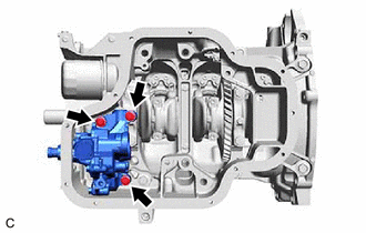
7. REMOVE OIL PUMP ASSEMBLY
| (a) Remove the 3 bolts and oil pump assembly from the stiffening crankcase assembly. |
|
8. REMOVE STIFFENING CRANKCASE ASSEMBLY
Click here
READ NEXT:
 Disassembly
DISASSEMBLY PROCEDURE 1. REMOVE OIL PUMP RELIEF VALVE (a) Using a 27 mm socket wrench, remove the oil pump relief valve plug from the oil pump cover sub-assembly. *1 Oil Pump Relief
Inspection
INSPECTION PROCEDURE 1. INSPECT OIL PUMP RELIEF VALVE (a) Coat the oil pump relief valve with engine oil, then check that it falls smoothly into the valve hole by its own weight. HINT: If the oil p
Reassembly
REASSEMBLY PROCEDURE 1. INSTALL OIL PUMP REGULATOR RING (a) Install the oil pump regulator ring to the oil pump body. *1 Oil Pump Regulator Vane *2 Oil Pump Regulator Ring
SEE MORE:
Installation
INSTALLATION CAUTION / NOTICE / HINT HINT:
Use the same procedure for the RH side and LH side.
The following procedure is for the LH side.
PROCEDURE 1. PRECAUTION NOTICE: After turning the engine switch (for Gasoline Model) or power switch (for HV Model) off, waiting time may be required bef
Diagnostic Trouble Code Chart
DIAGNOSTIC TROUBLE CODE CHART Power Trunk Lid System DTC No. Detection Item Link B2205 Kick Sensor Circuit B2222 PBD/PTL Pulse Sensor B2225 PBD/PTL Motor Clutch Malfunction B2250 PBD/PTL Closer Operation B2251 PBD/PTL Closer Switch U0
