Lexus ES: Removal
REMOVAL
CAUTION / NOTICE / HINT
The necessary procedures (adjustment, calibration, initialization or registration) that must be performed after parts are removed and installed, or replaced during direct fuel injector assembly removal/installation are shown below.
Necessary Procedures After Parts Removed/Installed/Replaced| Replaced Part or Performed Procedure | Necessary Procedure | Effect/Inoperative Function when Necessary Procedure not Performed | Link |
|---|---|---|---|
|
*: When performing learning using the Techstream.
Click here | |||
| Auxiliary battery terminal is disconnected/reconnected | Perform steering sensor zero point calibration | Lane Control System (for HV Model) | |
| Pre-collision System (for HV Model) | |||
| Parking Support Brake System (for HV Model)* | |||
| Lighting System (for HV Model) | |||
| Memorize steering angle neutral point | Parking Assist Monitor System (for HV Model) | | |
| Panoramic View Monitor System (for HV Model) | | ||
| Initialize power trunk lid system | Power Trunk Lid System (for HV Model) | | |
| Inspection after repair |
| |
CAUTION:
-
Never perform work on fuel system components near any possible ignition sources.
.png)
- Vaporized fuel could ignite, resulting in a serious accident.
-
Do not perform work on fuel system components without first disconnecting the cable from the negative (-) auxiliary battery terminal.
.png)
- Sparks could cause vaporized fuel to ignite, resulting in a serious accident.
-
To prevent serious injury due to fuel spray from the high-pressure fuel lines, always discharge fuel system pressure before removing any fuel system components.
.png)
NOTICE:
- After the power switch is turned off, the radio receiver assembly records various types of memory and settings. As a result, after turning the power switch off, make sure to wait at least 85 seconds before disconnecting the cable from the negative (-) auxiliary battery terminal. (for Audio and Visual System)
- After the power switch is turned off, the radio receiver assembly records various types of memory and settings. As a result, after turning the power switch off, make sure to wait at least 85 seconds before disconnecting the cable from the negative (-) auxiliary battery terminal. (for Navigation System)
-
This procedure includes the removal of small-head bolts. Refer to Small-Head Bolts of Basic Repair Hint to identify the small-head bolts.
Click here
.gif)
PROCEDURE
1. PRECAUTION
NOTICE:
After turning the power switch off, waiting time may be required before disconnecting the cable from the negative (-) auxiliary battery terminal. Therefore, make sure to read the disconnecting the cable from the negative (-) auxiliary battery terminal notices before proceeding with work.
2. DISCHARGE FUEL SYSTEM PRESSURE
Click here
3. DISCONNECT CABLE FROM NEGATIVE AUXILIARY BATTERY TERMINAL
Click here
4. REMOVE INTAKE MANIFOLD
Click here
5. DISCONNECT FUEL TUBE SUB-ASSEMBLY
| (a) Remove the fuel pipe clamp from the fuel tube connector. |
|
| (b) Disconnect the fuel tube sub-assembly from the fuel pump assembly and fuel delivery pipe sub-assembly. Click here |
|
6. REMOVE NO. 1 FUEL PIPE SUB-ASSEMBLY
CAUTION:
To prevent serious injury due to fuel spray from the high-pressure fuel lines, always discharge fuel system pressure before removing any fuel system components.
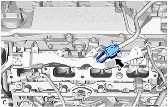
| (a) Disconnect the ignition coil connector. |
|
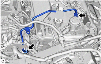
(b) for EGR Valve Bracket Connection Type:
| (1) Using a 17 mm union nut wrench, loosen the 2 union nuts of the No. 1 fuel pipe sub-assembly. |
|
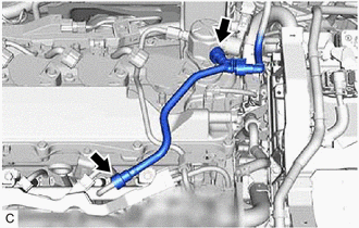
(c) for Cylinder Head Cover Sub-assembly Connection Type:
(1) Using a 17 mm union nut wrench, loosen the 2 union nuts of the No. 1 fuel pipe sub-assembly.
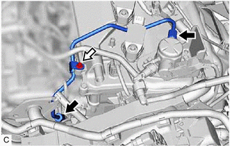
.png) | Union Nut |
.png) | Bolt |
(2) Using an 8 mm socket wrench, remove the bolt.
| (d) Loosen the 2 bolts of the fuel pump assembly. |
|
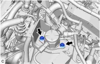
(e) Remove the No. 1 fuel pipe sub-assembly from the fuel delivery pipe and fuel pump assembly.
7. REMOVE FUEL PUMP ASSEMBLY
Click here
8. REMOVE FUEL DELIVERY PIPE
NOTICE:
When replacing the fuel delivery pipe, it is necessary to replace the No. 1 fuel pipe sub-assembly with a new one.
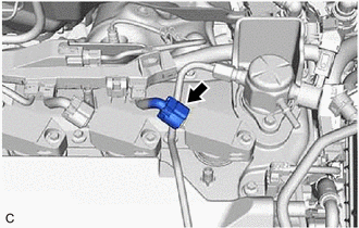
| (a) Disconnect the fuel pressure sensor connector. |
|
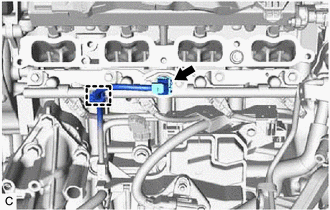
(b) Disengage the clamp to disconnect the sensor wire from the fuel delivery pipe.
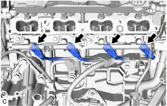
| (c) Disconnect the 4 direct fuel injector assembly connectors. NOTICE: Make sure to disconnect the connectors carefully. |
|
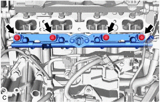
| (d) Remove the 4 bolts and fuel delivery pipe with the 4 direct fuel injector assemblies from the cylinder head sub-assembly. NOTICE:
|
|
9. REMOVE DIRECT FUEL INJECTOR ASSEMBLY
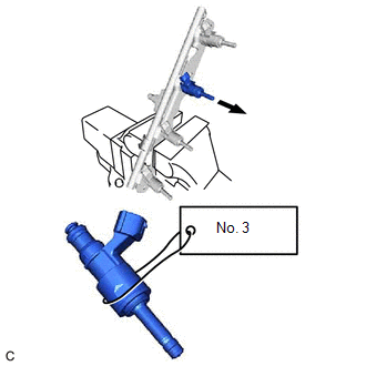
| (a) Secure the fuel delivery pipe in a vise between aluminum plates and pull out the 4 direct fuel injector assemblies. NOTICE:
|
|
(b) Remove the nozzle holder clamp from each direct fuel injector assembly.
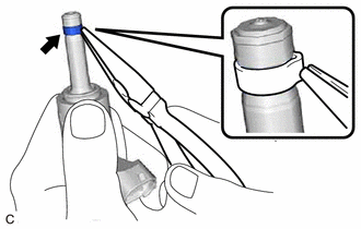
(c) Using needle nose pliers, remove the No. 3 fuel injector back-up ring from each direct fuel injector assembly.
NOTICE:
Do not damage the area that contacts the O-ring.
(d) Remove the O-ring and No. 1 fuel injector back-up ring from each direct fuel injector assembly.
(e) Remove the C-ring and injector vibration insulator from each direct fuel injector assembly.
10. REMOVE FUEL INJECTOR SEAL
| (a) Using the tip of needle nose pliers, pinch and pull the fuel injector seal at several points to stretch it. NOTICE:
|
|
(b) Remove the fuel injector seal from each direct fuel injector assembly.
READ NEXT:
 Inspection
INSPECTION PROCEDURE 1. INSPECT DIRECT FUEL INJECTOR ASSEMBLY NOTICE: This inspection is for checking the direct fuel injector assembly for an open or short. Because the direct fuel injector assembly
Installation
INSTALLATION CAUTION / NOTICE / HINT NOTICE: This procedure includes the installation of small-head bolts. Refer to Small-Head Bolts of Basic Repair Hint to identify the small-head bolts. Click here
SEE MORE:
Torque Converter Clutch Pressure Control Solenoid Control Circuit Short to Ground or Open (P275614)
DESCRIPTION Refer to DTC P275612. Click here DTC No. Detection Item DTC Detection Condition Trouble Area MIL Memory Note P275614 Torque Converter Clutch Pressure Control Solenoid Control Circuit Short to Ground or Open While the vehicle is being driven, a short to ground or
Fail-safe Chart
FAIL-SAFE CHART PROTECTION FUNCTION (a) The windshield wiper motor assembly operates the following protection functions if it detects an abnormal condition, in order to protect the wiper and washer system. Item Protection Content Conditions to Return to Normal Condition Overheat protectio
