Lexus ES: Removal
REMOVAL
CAUTION / NOTICE / HINT
The necessary procedures (adjustment, calibration, initialization, or registration) that must be performed after parts are removed and installed, or replaced during rear crankshaft oil seal removal/installation are shown below.
Necessary Procedure After Parts Removed/Installed/Replaced| Replaced Part or Performed Procedure | Necessary Procedure | Effect/Inoperative Function when Necessary Procedure not Performed | Link |
|---|---|---|---|
| Auxiliary battery terminal is disconnected/reconnected | Perform steering sensor zero point calibration | Lane control system (for HV Model) | |
| Pre-collision system (for HV Model) | |||
| Parking support brake system (for HV Model)* | |||
| Lighting system (for HV Model) | |||
| Memorize steering angle neutral point | Parking assist monitor system (for HV Model) | | |
| Panoramic view monitor system (for HV Model) | | ||
| Initialize power trunk lid system | Power trunk lid system (for HV Model) | | |
| Replacement of ECM | Perform Vehicle Identification Number (VIN) registration | MIL illuminates | |
| Inspection After Repair |
| |
| Replacement of inverter with converter assembly | Resolver learning |
| |
| Replacement of hybrid vehicle transaxle assembly |
| ||
| Front wheel alignment adjustment |
|
| |
|
|
| |
| Suspension, tires, etc.*1 | Rear television camera assembly optical axis (Back camera position setting) | Parking assist monitor system (for HV Model) | |
| Replacement of front bumper assembly | Front television camera view adjustment | Panoramic view monitor system (for HV Model) | |
| Suspension, tires, etc.*1 |
| ||
| Replacement of headlight ECU sub-assembly LH |
| Lighting system (for HV Model) | |
| Suspension, tires, etc.*1 | Perform headlight ECU sub-assembly LH initialization*2 |
-
*: When performing learning using the Techstream.
Click here
.gif)
- *1: If the vehicle height has changed due to suspension or tire replacement.
- *2: for LED type turn signal light
NOTICE:
- After the power switch is turned off, the radio receiver assembly records various types of memory and settings. As a result, after turning the power switch off, make sure to wait at least 85 seconds before disconnecting the cable from the negative (-) auxiliary battery terminal. (for Audio and Visual System)
- After the power switch is turned off, the radio receiver assembly records various types of memory and settings. As a result, after turning the power switch off, make sure to wait at least 85 seconds before disconnecting the cable from the negative (-) auxiliary battery terminal. (for Navigation System)
-
This procedure includes the removal of small-head bolts. Refer to Small-Head Bolts of Basic Repair Hint to identify the small-head bolts.
Click here
PROCEDURE
1. REMOVE HYBRID VEHICLE TRANSAXLE ASSEMBLY
Click here
2. REMOVE TRANSMISSION INPUT DAMPER ASSEMBLY
(a) Using height adjustment attachments and plate lift attachments, place the engine assembly on a flat level surface.
NOTICE:
- Using height adjustment attachments and plate lift attachments, keep the engine assembly horizontal.
- To prevent the No. 2 oil pan sub-assembly from deforming, do not place any attachments under the No. 2 oil pan sub-assembly of the engine assembly.
- Using an engine sling device and engine lift, secure the engine assembly before servicing.
| (b) Using SST, hold the crankshaft pulley assembly. SST: 09213-54015 SST: 09330-00021 |
|
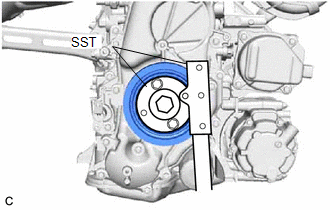
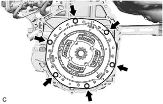
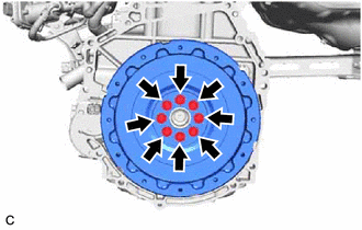
| (c) Remove the 6 bolts and transmission input damper assembly from the flywheel sub-assembly. |
|
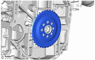
3. REMOVE FLYWHEEL SUB-ASSEMBLY
| (a) Using SST, hold the crankshaft pulley assembly. SST: 09213-54015 SST: 09330-00021 |
|

| (b) Remove the 8 bolts and flywheel sub-assembly from the crankshaft. |
|
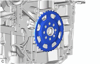
4. REMOVE NO. 1 CRANKSHAFT POSITION SENSOR PLATE
(a) Type A:
| (1) Remove the No. 1 crankshaft position sensor plate. |
|
(b) Type B:
| (1) Remove the No. 1 crankshaft position sensor plate. |
|
5. REMOVE REAR ENGINE OIL SEAL
| (a) Using a knife, cut off the lip of the rear engine oil seal. |
|
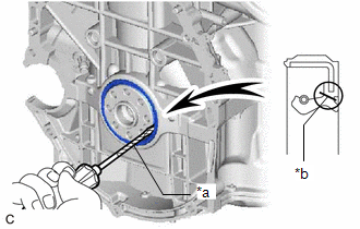
(b) Using a screwdriver with its tip wrapped with protective tape, pry out the rear engine oil seal.
NOTICE:
Be careful not to damage the crankshaft.
READ NEXT:
 Installation
INSTALLATION CAUTION / NOTICE / HINT NOTICE: This procedure includes the installation of small-head bolts. Refer to Small-Head Bolts of Basic Repair Hint to identify the small-head bolts. Click here
SEE MORE:
Removal
REMOVAL
PROCEDURE
1. REMOVE COWL TOP VENTILATOR LOUVER SUB-ASSEMBLY
Click here
2. REMOVE FRONT CENTER UPPER SUSPENSION BRACE SUB-ASSEMBLY
Click here
3. REMOVE UNION TO CHECK VALVE HOSE
(a) Disengage the clamp to separate the union to check valve hose from
the air tube.
How To Proceed With Troubleshooting
CAUTION / NOTICE / HINT HINT:
Use the following procedure to troubleshoot the power steering system.
*: Use the Techstream.
PROCEDURE 1. VEHICLE BROUGHT TO WORKSHOP
NEXT 2. INSPECT AUXILIARY BATTERY (a) Turn the power switch off. (b) Measure the voltage of
