Lexus ES: Removal
REMOVAL
CAUTION / NOTICE / HINT
The necessary procedures (adjustment, calibration, initialization, or registration) that must be performed after parts are removed and installed, or replaced during engine unit removal/installation are shown below.
Necessary Procedure After Parts Removed/Installed/Replaced| Replaced Part or Performed Procedure | Necessary Procedure | Effect/Inoperative Function when Necessary Procedure not Performed | Link |
|---|---|---|---|
| Auxiliary battery terminal is disconnected/reconnected | Perform steering sensor zero point calibration | Lane control system (for HV Model) | |
| Pre-collision system (for HV Model) | |||
| Parking support brake system (for HV Model)* | |||
| Lighting system (for HV Model) | |||
| Memorize steering angle neutral point | Parking assist monitor system (for HV Model) | | |
| Panoramic view monitor system (for HV Model) | | ||
| Initialize power trunk lid system | Power trunk lid system (for HV Model) | | |
| Replacement of ECM | Perform Vehicle Identification Number (VIN) registration | MIL illuminates (for HV Model) | |
| Inspection After Repair |
| |
| Replacement of inverter with converter assembly | Resolver learning |
| |
| Replacement of hybrid vehicle transaxle assembly |
| ||
| Front wheel alignment adjustment |
|
| |
|
|
| |
| Suspension, tires, etc.*1 | Rear television camera assembly optical axis (Back camera position setting) | Parking assist monitor system (for HV Model) | |
| Replacement of front bumper assembly | Front television camera view adjustment | Panoramic view monitor system (for HV Model) | |
| Suspension, tires, etc.*1 |
| ||
| Replacement of headlight ECU sub-assembly LH |
| Lighting system (for HV Model) | |
| Suspension, tires, etc.*1 | Perform headlight ECU sub-assembly LH initialization*2 |
-
*: When performing learning using the Techstream.
Click here
.gif)
- *1: If the vehicle height has changed due to suspension or tire replacement.
- *2: for LED type turn signal light
NOTICE:
- After the power switch is turned off, the radio receiver assembly records various types of memory and settings. As a result, after turning the power switch off, make sure to wait at least 85 seconds before disconnecting the cable from the negative (-) auxiliary battery terminal. (for Audio and Visual System)
- After the power switch is turned off, the radio receiver assembly records various types of memory and settings. As a result, after turning the power switch off, make sure to wait at least 85 seconds before disconnecting the cable from the negative (-) auxiliary battery terminal. (for Navigation System)
-
This procedure includes the removal of small-head bolts. Refer to Small-Head Bolts of Basic Repair Hint to identify the small-head bolts.
Click here
PROCEDURE
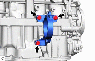
1. REMOVE DRIVE SHAFT BEARING BRACKET
| (a) Remove the 3 bolts and drive shaft bearing bracket. |
|
2. REMOVE COMPRESSOR WITH MOTOR ASSEMBLY
(a) Remove the bolt and 2 nuts.
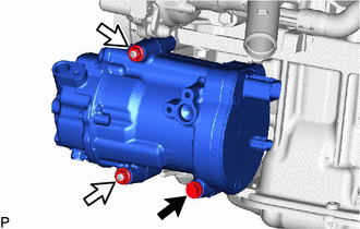
.png) | Bolt |
.png) | Nut |
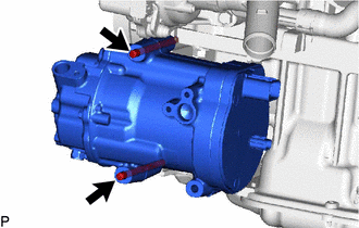
| (b) Using an E8 "TORX" socket wrench, remove the 2 stud bolts and compressor with motor assembly. |
|
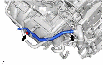
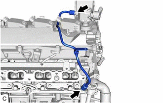
3. REMOVE NO. 2 WATER BY-PASS PIPE SUB-ASSEMBLY
| (a) Slide the clip and disconnect the No. 2 water by-pass pipe sub-assembly from the outlet water by-pass sub-assembly. |
|
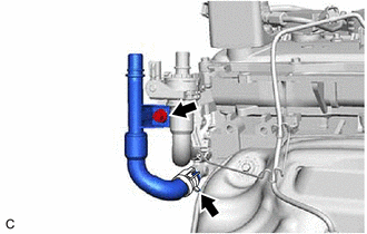
(b) Remove the bolt and the No. 2 water by-pass pipe sub-assembly.
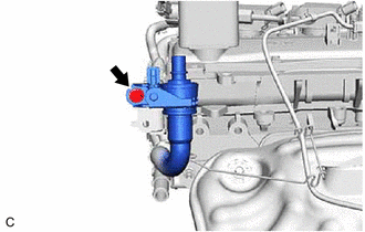
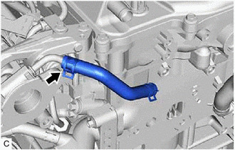
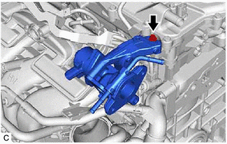
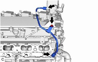
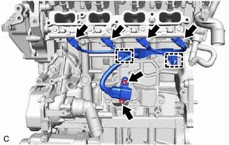
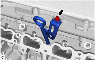
4. REMOVE FLOW SHUTTING VALVE (WATER BY-PASS HOSE ASSEMBLY)
| (a) Remove the bolt. |
|
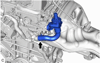
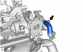
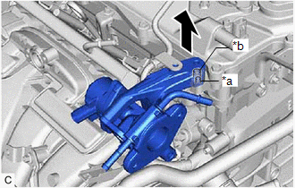
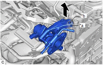
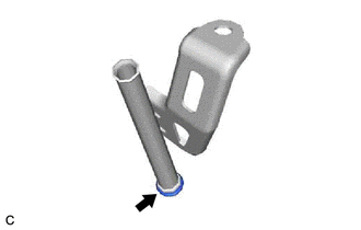
| (b) Slide the clip and remove the flow shutting valve (water by-pass hose assembly) from the water by-pass outlet sub-assembly. |
|
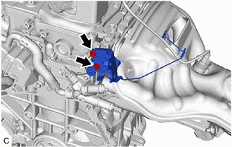
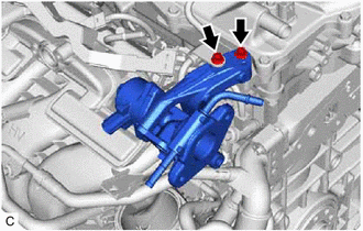
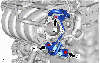
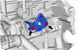
| (c) Remove the 2 bolts and water hose clamp bracket. |
|
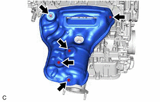
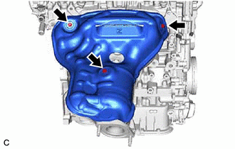
5. REMOVE NO. 1 EXHAUST MANIFOLD HEAT INSULATOR
(a) Type A:
| (1) Remove the 5 bolts and No. 1 exhaust manifold heat insulator from the exhaust manifold (TWC: Front Catalyst). |
|
(b) Type B:
| (1) Remove the 3 bolts and No. 1 exhaust manifold heat insulator from the exhaust manifold (TWC: Front Catalyst). |
|
6. REMOVE MANIFOLD STAY
Click here
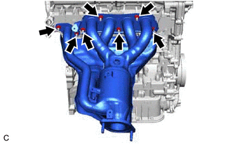
7. REMOVE EXHAUST MANIFOLD (TWC: Front Catalyst)
(a) Type A:
| (1) Using a 12 mm deep socket wrench, remove the 7 nuts and exhaust manifold (TWC: Front Catalyst) from the cylinder head sub-assembly. |
|
(b) Type B:
| (1) Using a 12 mm deep socket wrench, remove the 7 nuts and exhaust manifold (TWC: Front Catalyst) from the cylinder head sub-assembly. |
|

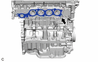
| (c) Remove the exhaust manifold to head gasket from the cylinder head sub-assembly. |
|
8. REMOVE THROTTLE BODY WITH MOTOR ASSEMBLY
Click here
9. REMOVE THROTTLE BODY GASKET
Click here
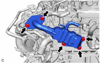
10. REMOVE EGR COOLER ASSEMBLY
| (a) Slide the clip and disconnect the No. 4 water by-pass hose from the EGR cooler assembly. |
|

(b) Slide the clip and disconnect the No. 3 water by-pass hose from the EGR cooler assembly.
| (c) Remove the 5 bolts, EGR cooler assembly, EGR cooler gasket and EGR valve gasket. |
|
11. REMOVE NO. 1 EGR PIPE SUB-ASSEMBLY
Click here
12. REMOVE NO. 4 WATER BY-PASS HOSE
| (a) Slide the clip and remove the No. 4 water by-pass hose from the EGR valve assembly. |
|
13. REMOVE EGR VALVE ASSEMBLY
| (a) Slide the clip and disconnect the No. 8 water by-pass hose from the EGR valve assembly. |
|
(b) for EGR Valve Bracket Connection Type:
| (1) Using an 8 mm socket wrench, remove the bolt and disconnect the No. 1 fuel pipe sub-assembly from the EGR valve bracket. |
|
(2) Using an 8 mm socket wrench, remove the bolt.
| (3) Remove the EGR valve assembly vertically. |
|
(c) for Cylinder Head Cover Sub-assembly Connection Type:
| (1) Using an 8 mm socket wrench, remove the bolt. |
|
| (2) Remove the EGR valve assembly vertically. |
|
| (d) Using an 8 mm socket wrench, remove the bolt and EGR valve bracket. |
|

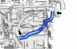
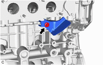
14. REMOVE NO. 3 WATER BY-PASS PIPE
| (a) Using an 8 mm socket wrench, remove the bolt and No. 3 water by-pass pipe from the intake manifold. |
|
(b) Slide the clip and disconnect the No. 3 water by-pass pipe from the water outlet.
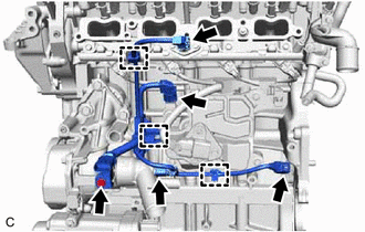
15. REMOVE NO. 2 WATER BY-PASS PIPE
| (a) Remove the bolt (A). |
|
(b) Using an 8 mm socket wrench, remove the 2 bolts (B) and No. 2 water by-pass pipe.
16. REMOVE INTAKE MANIFOLD
Click here
17. REMOVE NO. 1 INTAKE MANIFOLD TO HEAD GASKET
Click here
18. DISCONNECT FUEL TUBE SUB-ASSEMBLY
Click here
19. REMOVE NO. 1 FUEL PIPE SUB-ASSEMBLY
(a) for EGR Valve Bracket Connection Type:
| (1) Using a 17 mm union nut wrench, loosen the 2 union nuts of the No. 1 fuel pipe sub-assembly. |
|
(b) for Cylinder Head Cover Sub-assembly Connection Type:
| (1) Using an 8 mm socket wrench, remove the bolt. |
|
(2) Using a 17 mm union nut wrench, loosen the 2 union nuts of the No. 1 fuel pipe sub-assembly.
20. REMOVE FUEL (ENGINE ROOM SIDE) PUMP ASSEMBLY (for High Pressure)
Click here
21. REMOVE NO. 7 WATER BY-PASS HOSE
| (a) Slide the 2 clips and remove the No. 7 water by-pass hose. |
|
22. REMOVE SENSOR WIRE
| (a) Disconnect the 4 connectors. |
|
(b) Disengage the 3 clamps.
(c) Using an 8 mm socket wrench, remove the bolt and sensor wire from the water inlet with thermostat sub-assembly.
23. REMOVE NO. 6 ENGINE WIRE
| (a) Disconnect the 4 connectors. |
|
(b) Disengage the 2 clamps.
(c) Remove the 2 nuts and No. 6 engine wire from the wire harness clamp bracket.
24. REMOVE WIRE HARNESS CLAMP BRACKET
| (a) Using an 8 mm socket wrench, remove the 2 bolts and wire harness clamp bracket from the No. 1 ventilation case. |
|
25. REMOVE FUEL DELIVERY PIPE SUB-ASSEMBLY
Click here
26. REMOVE NO. 1 DELIVERY PIPE SPACER
Click here
27. REMOVE INJECTOR VIBRATION INSULATOR
Click here
28. REMOVE NO. 5 ENGINE WIRE
Click here
29. REMOVE PORT FUEL INJECTOR ASSEMBLY
Click here
30. REMOVE FUEL DELIVERY PIPE
Click here
31. REMOVE DIRECT FUEL INJECTOR ASSEMBLY
Click here
32. REMOVE IGNITION COIL ASSEMBLY
Click here
33. REMOVE ENGINE OIL LEVEL DIPSTICK GUIDE
(a) Remove the engine oil level dipstick.
| (b) Using an 8 mm socket wrench, remove the bolt and engine oil level dipstick guide from the camshaft housing sub-assembly. |
|
| (c) Remove the O-ring from the engine oil level dipstick guide. |
|
34. REMOVE NO. 3 EXHAUST MANIFOLD HEAT INSULATOR
(a) Type A:
| (1) Remove the bolt and No. 3 exhaust manifold heat insulator from the cylinder block sub-assembly. |
|
(b) Type B:
| (1) Remove the 2 bolts and No. 3 exhaust manifold heat insulator from the cylinder block sub-assembly. |
|

READ NEXT:
 Disassembly
DISASSEMBLY CAUTION / NOTICE / HINT NOTICE: This procedure includes the removal of small-head bolts. Refer to Small-Head Bolts of Basic Repair Hint to identify the small-head bolts. Click here PROCE
Inspection
INSPECTION PROCEDURE 1. INSPECT NO. 1 VALVE ROCKER ARM SUB-ASSEMBLY (a) Turn the roller by hand to check that it turns smoothly. HINT: If the roller does not turn smoothly, replace the No. 1 valve
Reassembly
REASSEMBLY CAUTION / NOTICE / HINT NOTICE: This procedure includes the installation of small-head bolts. Refer to Small-Head Bolts of Basic Repair Hint to identify the small-head bolts. Click here P
SEE MORE:
Terminals Of Ecu
TERMINALS OF ECU CHECK INSTRUMENT PANEL JUNCTION BLOCK ASSEMBLY AND MAIN BODY ECU (MULTIPLEX NETWORK BODY ECU) (a) Disconnect the MB main body ECU (multiplex network body ECU) connector. Click here (b) Measure the voltage and resistance according to the value(s) in the table below. HINT: Measure
How To Proceed With Troubleshooting
CAUTION / NOTICE / HINT HINT:
Use the following procedure to troubleshoot the window defogger system.
*: Use the Techstream.
PROCEDURE 1. VEHICLE BROUGHT TO WORKSHOP
NEXT 2. CUSTOMER PROBLEM ANALYSIS HINT:
In troubleshooting, confirm that the problem sym
