Lexus ES: Removal
REMOVAL
CAUTION / NOTICE / HINT
The necessary procedures (adjustment, calibration, initialization or registration) that must be performed after parts are removed and installed, or replaced during mass air flow meter sub-assembly removal/installation are shown below.
Necessary Procedures After Parts Removed/Installed/Replaced| Replaced Part or Performed Procedure | Necessary Procedure | Effect/Inoperative Function when Necessary Procedure not Performed | Link |
|---|---|---|---|
| Replacement of mass air flow meter sub-assembly | Inspection after repair |
| |
.gif)
PROCEDURE
1. REMOVE MASS AIR FLOW METER SUB-ASSEMBLY
| (a) Disconnect the mass air flow meter sub-assembly connector. |
|
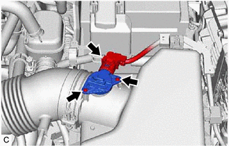
(b) Remove the 2 screws and mass air flow meter sub-assembly from the air cleaner cap sub-assembly.
NOTICE:
If the mass air flow meter sub-assembly has been struck or dropped, replace it.
READ NEXT:
 Inspection
INSPECTION PROCEDURE 1. INSPECT MASS AIR FLOW METER SUB-ASSEMBLY (a) Perform a visual check for any foreign matter on the intake air temperature sensor (thermistor) of the mass air flow meter sub-a
Installation
INSTALLATION PROCEDURE 1. INSTALL MASS AIR FLOW METER SUB-ASSEMBLY HINT: Perform "Inspection After Repair" after replacing the mass air flow meter sub-assembly. Click here (a) Install the mass air f
Relay
On-vehicle InspectionON-VEHICLE INSPECTION PROCEDURE 1. INSPECT MAIN RELAY (EFI-MAIN NO. 1) (a) Measure the resistance according to the value(s) in the table below. Standard Resistance: Tester
SEE MORE:
Components
COMPONENTS ILLUSTRATION *1 COURTESY LIGHT ASSEMBLY *2 REAR DOOR TRIM BOARD SUB-ASSEMBLY *3 REAR DOOR UPPER TRIM PAD *4 REAR POWER WINDOW REGULATOR SWITCH ASSEMBLY WITH REAR DOOR UPPER ARMREST BASE PANEL ILLUSTRATION *A w/ Rear Door Sunshade - - *1 CURTAIN HOOK
Inspection
INSPECTION PROCEDURE 1. INSPECT HYBRID BATTERY TERMINAL BLOCK (a) Measure the resistance according to the value(s) in the table below. Standard Resistance: Tester Connection Condition Specified Condition Hybrid Battery Terminal Block Always Below 1 Ω If the result is not as sp
