Lexus ES: Removal
REMOVAL
CAUTION / NOTICE / HINT
The necessary procedures (adjustment, calibration, initialization, or registration) that must be performed after parts are removed and installed, or replaced during steering knuckle removal/installation are shown below.
Necessary Procedures After Parts Removed/Installed/Replaced (for HV Model:)| Replaced Part or Performed Procedure | Necessary Procedure | Effect/Inoperative Function when Necessary Procedure not Performed | Link |
|---|---|---|---|
|
*: When performing learning using the Techstream.
Click here | |||
| Auxiliary battery terminal is disconnected/reconnected | Perform steering sensor zero point calibration | Lane Control System | |
| Pre-collision System | |||
| Parking Support Brake System* | |||
| Lighting System | |||
| Memorize steering angle neutral point | Parking Assist Monitor System | | |
| Panoramic View Monitor System | | ||
| Initialize power trunk lid system | Power Trunk Lid System (for HV Model) | | |
| Front wheel alignment adjustment |
|
| |
NOTICE:
for HV Model:- After the power switch is turned off, the radio receiver assembly records various types of memory and settings. As a result, after turning the power switch off, make sure to wait at least 85 seconds before disconnecting the cable from the negative (-) auxiliary battery terminal. (for Audio and Visual System)
- After the power switch is turned off, the radio receiver assembly records various types of memory and settings. As a result, after turning the power switch off, make sure to wait at least 85 seconds before disconnecting the cable from the negative (-) auxiliary battery terminal. (for Navigation System)
CAUTION / NOTICE / HINT
Necessary Procedures After Parts Removed/Installed/Replaced (for Gasoline Model:)| Replaced Part or Performed Procedure | Necessary Procedure | Effect/Inoperative Function when Necessary Procedure not Performed | Link |
|---|---|---|---|
| Front wheel alignment adjustment |
|
| |
- When removing or installing the front disc brake caliper assembly, pushing back the disc brake piston may cause a large clearance between the brake pads and brake disc. When the brake pedal is depressed with a large clearance between the brake pads and the brake disc, DTC C1214 related to abnormal brake fluid pressure may be stored. Make sure to clear any DTCs after performing this procedure.
- While the auxiliary battery is connected, even if the power switch is off, the brake control system activates when the brake pedal is depressed or any door courtesy switch turns on. Therefore, when servicing the brake system components, do not operate the brake pedal or open/close the doors while the auxiliary battery is connected.
HINT:
- Use the same procedure for the RH side and LH side.
- The following procedure is for the LH side.
PROCEDURE
1. REMOVE FRONT AXLE ASSEMBLY
Click here .gif)
2. REMOVE FRONT LOWER BALL JOINT ASSEMBLY
Click here
3. REMOVE STEERING KNUCKLE
| (a) Secure the front axle assembly between aluminum plates in a vise. NOTICE: Do not overtighten the vise. |
|
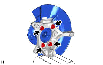
(b) Remove the 4 bolts, front axle hub sub-assembly and front disc brake dust cover from the steering knuckle.
NOTICE:
- Do not drop the front axle hub sub-assembly.
- Be careful not to damage the speed sensor rotor or contact surfaces.
- Do not allow foreign matter to contact the speed sensor rotor or contact surfaces.
READ NEXT:
 Drive Shaft System
PrecautionPRECAUTION NOTICE OF REMOVING AND INSTALLING FRONT DRIVE SHAFT ASSEMBLY RH (for AWD) (a) When removing and installing the front drive shaft assembly RH in an AWD vehicle, be sure to first d
SEE MORE:
Open in Outer Mirror Indicator(Master) (C1AB4)
DESCRIPTION This DTC is stored when the blind spot monitor sensor RH detects an open in the outer rear view mirror indicator RH. DTC No. Detection Item DTC Detection Condition Trouble Area C1AB4 Open in Outer Mirror Indicator(Master) Both of the following conditions are met:
The
Reassembly
REASSEMBLY PROCEDURE 1. INSTALL REAR BUMPER REINFORCEMENT Click here 2. INSTALL REAR BUMPER PROTECTOR INSERT LH Click here 3. INSTALL REAR BUMPER PROTECTOR INSERT RH HINT: Use the same procedure as for the LH side. 4. INSTALL REAR BUMPER PROTECTOR LH Click here 5. INSTALL REAR BUMPER PROTECTOR
