Lexus ES: Electric Parking Brake Switch
Components
COMPONENTS
ILLUSTRATION
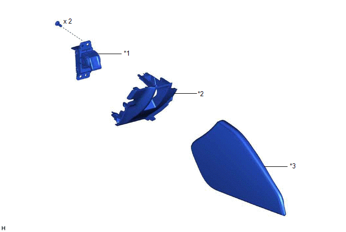
| *1 | ELECTRIC PARKING BRAKE SWITCH ASSEMBLY | *2 | LOWER INSTRUMENT PANEL |
| *3 | INSTRUMENT PANEL FINISH PANEL END | - | - |
Inspection
INSPECTION
PROCEDURE
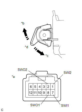
1. INSPECT ELECTRIC PARKING BRAKE SWITCH ASSEMBLY
(a) Check the resistance.
| (1) Measure the resistance according to the value(s) in the table below. Standard Resistance:
If the result is not as specified, replace the electric parking brake switch assembly. |
|
Removal
REMOVAL
PROCEDURE
1. PRECAUTION
Click here .gif)
2. REMOVE INSTRUMENT PANEL FINISH PANEL END
Click here
3. REMOVE LOWER INSTRUMENT PANEL
Click here
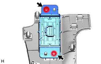
4. REMOVE ELECTRIC PARKING BRAKE SWITCH ASSEMBLY
| (a) Remove the 2 screws and electric parking brake switch assembly. |
|
READ NEXT:
 Brake Warning Light (Yellow) Remains On
DESCRIPTION This procedure is for troubleshooting when the brake warning light (yellow) remains on but no DTCs are output. The skid control ECU (brake actuator assembly) controls the brake warning lig
Electric Parking Brake Actuator (C13B800)
DESCRIPTION DTC No. Detection Item DTC Detection Condition Trouble Area Memory Note C13B800 Electric Parking Brake Actuator
Diagnosis Condition:
Electric parking brake operatin
SEE MORE:
Lost Communication with Airbag System Control Module Signal Plausibility Failure (P310764)
DESCRIPTION Refer to the description for DTC P310711. Click here DTC No. Detection Item DTC Detection Condition Trouble Area MIL Warning Indicate P310764 Lost Communication with Airbag System Control Module Signal Plausibility Failure Abnormal communication signal: Communicati
Check For Intermittent Problems
CHECK FOR INTERMITTENT PROBLEMS CHECK FOR INTERMITTENT PROBLEMS (a) Perform a simulation test. (1) For the simulation test, reproduce the driving conditions that were present when the problem occurred. These conditions should be based on the customer's comments and freeze frame data that is recorded
