Lexus ES: Removal
REMOVAL
CAUTION / NOTICE / HINT
The necessary procedures (adjustment, calibration, initialization, or registration) that must be performed after parts are removed and installed, or replaced during parking assist ECU removal/installation are shown below.
Necessary Procedure After Parts Removed/Installed/Replaced (for HV Model)| Replaced Part or Performed Procedure | Necessary Procedure | Effect/Inoperative Function When Necessary Procedures are not Performed | Link |
|---|---|---|---|
| Parking assist ECU |
| Panoramic View Monitor System | |
.gif)
| Replaced Part or Performed Procedure | Necessary Procedure | Effect/Inoperative Function When Necessary Procedures are not Performed | Link |
|---|---|---|---|
| Parking assist ECU |
| Panoramic View Monitor System | |
PROCEDURE
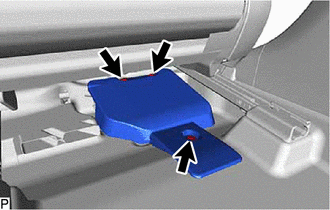
1. REMOVE PARKING ASSIST ECU COVER
(a) Operate the slide and vertical power seat switch knob and move the front seat assembly to the foremost position.
| (b) Remove the 3 clips and parking assist ECU cover. |
|
2. REMOVE PARKING ASSIST ECU
| (a) Disconnect each connector. |
|
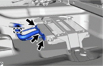
(b) Disengage the clamp.
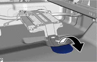
| (c) Turn back the front floor carpet assembly as shown in the illustration. |
|
| (d) Remove the bolt. |
|
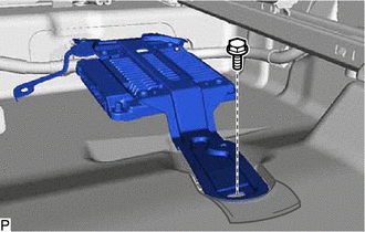
(e) Disengage the 2 guides and remove the parking assist ECU as shown in the illustration.
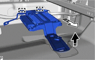
.png) | Remove in this Direction (1) |
.png) | Remove in this Direction (2) |
READ NEXT:
 Black Screen
DESCRIPTION The video signal from the rear television camera assembly is transmitted to the multi-display assembly. WIRING DIAGRAM CAUTION / NOTICE / HINT NOTICE:
If the cable was disconnected fro
Vehicle Information Unmatched (C168D)
DESCRIPTION This DTC is stored if the rear television camera assembly judges as a result of its self check that the vehicle information received from the main body ECU (multiplex network body ECU) via
SEE MORE:
How To Proceed With Troubleshooting
CAUTION / NOTICE / HINT HINT:
Before performing troubleshooting for the front camera system, perform troubleshooting for the pre-collision system.
Click here
If a pre-collision system related warning message is displayed on the multi-information display, refer to How to Proceed with Troublesh
Abnormal Power Supply Voltage in Yaw Rate and/or Deceleration Sensor (C1381)
DESCRIPTION The airbag ECU assembly has a built-in yaw rate and acceleration sensor and detects the vehicle condition using 2 circuits (GL1, GL2). If a power source malfunction signal from the yaw rate and acceleration sensor (airbag ECU assembly) is detected by the skid control ECU (brake booster w
