Lexus ES: Reassembly
REASSEMBLY
PROCEDURE
1. INSTALL SUNSHADE TRIM SUB-ASSEMBLY
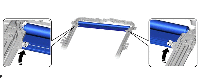
| (a) Make sure that the No. 1 sliding roof shoe sub-assembly is positioned as shown in the illustration. HINT: Use the same procedure for the RH side and LH side. |
|
(b) Install the sunshade trim sub-assembly as shown in the illustration.
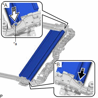
| *A | RH Side |
| *B | LH Side |
| *a | Retractor Cap |
.png) | Install in this Direction (1) |
.png) | Install in this Direction (2) |
NOTICE:
To prevent the sunshade trim sub-assembly from being damaged, fully push in the RH side retractor cap when installing the sunshade trim sub-assembly.
HINT:
Connect the LH side first.
(c) Insert the sunshade trim sub-assembly to the sliding roof drive rail sub-assembly LH as shown in the illustration.
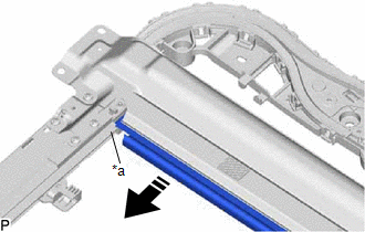
| *a | Sliding Roof Drive Rail Sub-assembly LH |
| | Install in this Direction |
HINT:
Use the same procedure for the RH side and LH side.
| (d) Install the sliding roof sunshade plate. HINT: Use the same procedure for the RH side and LH side. |
|
.png)
(e) Slide the sunshade trim sub-assembly as shown in the illustration to engage the 2 claws.
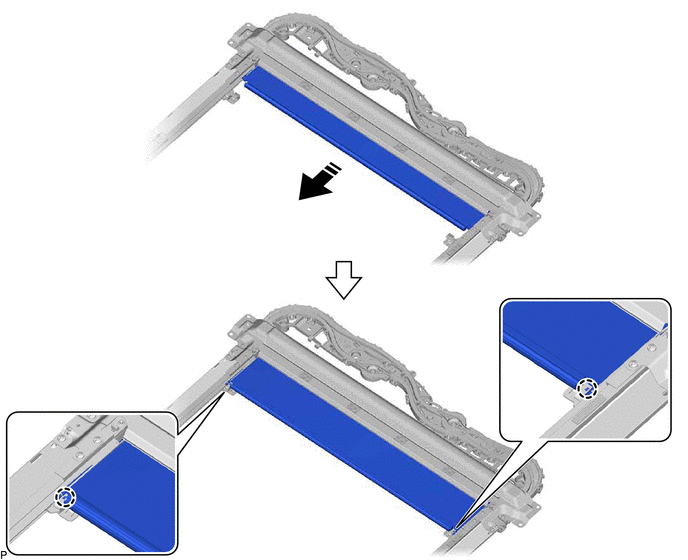
| | Install in this Direction | - | - |
(f) Move the sunshade trim sub-assembly as shown in the illustration to engage the 2 claws.
| | Install in this Direction | - | - |
2. INSTALL NO. 2 ROOF WIRE
(a) Engage the claw and 15 clamps to install the No. 2 roof wire.
.png)
(b) Prepare 2 new pieces of tape with the dimensions shown in the illustration.
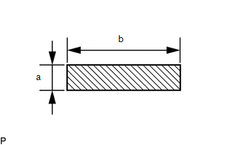
.png) | Tape |
Standard:
| Area | Specified Condition |
|---|---|
| a | 20 mm (0.787 in.) |
| b | 75 mm (2.95 in.) |
(c) Install the tape as shown in the illustration.
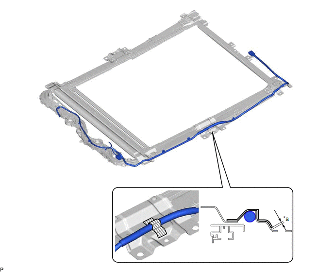
| *a | 3.0 mm (0.12 in.) or less | - | - |
| | Tape | - | - |
3. INSTALL REAR SLIDING ROOF GARNISH
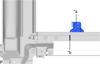
(a) Clean the sliding roof housing panel.
(1) Using a heat light, heat the sliding roof housing panel.
Heating Temperature| Item | Temperature |
|---|---|
| Sliding Roof Housing Panel | 40 to 60°C (104 to 140°F) |
CAUTION:
- Do not touch the heat light and heated parts, touching the heat light may result in burns.
- Touching heated parts for a long time may result in burns.
.png)
| *a | Heated Part |
| *b | Heat Light |
NOTICE:
Do not heat the sliding roof housing panel excessively.
(2) Remove the double-sided tape from the sliding roof housing panel.
(3) Clean off any tape adhesive residue with cleaner.
(b) Coat the installation area of the sliding roof housing panel with primer.
(c) Remove the release paper from a new rear sliding roof garnish.
HINT:
After removing the release paper, keep the exposed adhesive free from foreign matter.
(d) Engage the 2 guides to install the rear sliding roof garnish.
.png)
| | Double-sided Tape | - | - |
4. INSTALL SLIDE ROOF RAIL SUB-ASSEMBLY
(a) Install the slide roof rail sub-assembly with the 14 nuts.
.png)
Torque:
6.25 N·m {64 kgf·cm, 55 in·lbf}
5. INSTALL SLIDING ROOF DRIVE GEAR ASSEMBLY (for Sliding Roof Glass)
(a) Apply MP grease to the gear of the sliding roof drive gear assembly.
| (b) Install the sliding roof drive gear assembly with the 2 bolts. Torque: 5.4 N·m {55 kgf·cm, 48 in·lbf} |
|
.png)
(c) Connect the connector.
6. INSTALL SLIDING ROOF DRIVE GEAR ASSEMBLY (for Roof Sunshade)
(a) Apply MP grease to the gear of the sliding roof drive gear assembly.
| (b) Install the sliding roof drive gear assembly with the 2 bolts. Torque: 5.4 N·m {55 kgf·cm, 48 in·lbf} |
|
.png)
(c) Connect the connector.
| (d) Install the room light bracket with the 2 nuts. Torque: 6.25 N·m {64 kgf·cm, 55 in·lbf} |
|
.png)
7. INSTALL NO. 2 ROOM LIGHT BRACKET
| (a) Install the No. 2 room light bracket with the 2 nuts. Torque: 6.25 N·m {64 kgf·cm, 55 in·lbf} |
|
.png)
8. INSTALL ROOM LIGHT BRACKET
| (a) Install the room light bracket with the 2 nuts. Torque: 6.25 N·m {64 kgf·cm, 55 in·lbf} |
|
.png)
9. INSTALL ROOF WIND DEFLECTOR PANEL SUB-ASSEMBLY
(a) Move the roof wind deflector panel sub-assembly in the direction indicated by the arrow (1) shown in the illustration to engage the 2 guides.
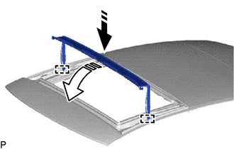
| | Install in this Direction (1) |
| | Install in this Direction (2) |
(b) Move the roof wind deflector panel sub-assembly in the direction indicated by the arrow (2) shown in the illustration.
(c) Engage the 2 pins and 3 claws to install the roof wind deflector panel sub-assembly.
.png)
READ NEXT:
 Installation
INSTALLATION PROCEDURE 1. INSTALL SLIDING ROOF OR REMOVABLE ROOF HOUSING SUB-ASSEMBLY (a) Pass a string under the windshield outside moulding as shown in the illustration. *1 Windshield Outside
Components
COMPONENTS ILLUSTRATION *1 SLIDING ROOF OR REMOVABLE ROOF PANEL SUB-ASSEMBLY *2 SLIDING ROOF SIDE GARNISH LH *3 SLIDING ROOF SIDE GARNISH RH *4 SLIDING ROOF WEATHERSTRIP *5 S
SEE MORE:
Headlight Swivel Motor LH (B2412,B2413,B2417,B2418)
DESCRIPTION The headlight ECU sub-assembly LH sends automatic headlight beam level control signals to each headlight swivel motor and headlight leveling motor via LIN communication. Each headlight ECU sub-assembly and headlight swivel motor and headlight leveling motor communicate via LIN communicat
High Pressure Fuel Pump Circuit Open (P123513)
DESCRIPTION The high-pressure direct injection fuel system consists of a spill control valve, check valve, fuel relief valve, fuel pressure sensor (for high pressure side), fuel pump assembly (for high pressure side) and direct fuel injector assemblies. The spill control valve adjusts the return vol
