Lexus ES: Rear Center Microphone Circuit Component Internal Failure (B1AAA96,B1AAB1C)
DESCRIPTION
These DTCs are stored when a malfunction occurs in the No. 3 active noise control microphone system.
| DTC No. | Detection Item | DTC Detection Condition | Trouble Area |
|---|---|---|---|
| B1AAA96 | Rear Center Microphone Circuit Component Internal Failure | Stereo component equalizer assembly detects malfunction in No. 3 active noise control microphone for 4 seconds or more continuously when engine speed is 1200 rpm or more* |
|
| B1AAB1C | Rear Center Microphone Circuit Circuit Voltage Out of Range | Stereo component equalizer assembly detects No. 3 active noise control microphone connection malfunction for 4 seconds or more continuously* |
|
HINT:
*: Malfunction monitoring is not performed under the following conditions, in order to prevent erroneous detection.
- After engine switch is turned on (ACC) for 3 seconds or more.
- After the battery voltage returns to normal for 3 seconds.
- Before 3 seconds have elapsed after battery voltage has returned to normal.
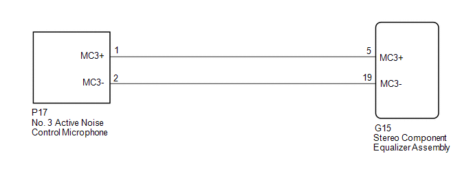
WIRING DIAGRAM
PROCEDURE
| 1. | CLEAR DTC |
(a) Clear the DTCs.
Body Electrical > Active Noise Control > Clear DTCs
|

| 2. | CHECK FOR DTC |
(a) Check for DTCs with all of the detection conditions met.
Body Electrical > Active Noise Control > Trouble CodesOK:
No DTCs are output.
| OK |  | USE SIMULATION METHOD TO CHECK |
|
| 3. | CHECK HARNESS AND CONNECTOR (STEREO COMPONENT EQUALIZER ASSEMBLY - NO. 3 ACTIVE NOISE CONTROL MICROPHONE) |
(a) Disconnect the G15 stereo component equalizer assembly connector.
(b) Disconnect the P17 No. 3 active noise control microphone connector.
(c) Measure the resistance according to the value(s) in the table below.
Standard Resistance:
| Tester Connection | Condition | Specified Condition |
|---|---|---|
| G15-5 (MC3+) - P17-1 (MC3+) | Always | Below 1 Ω |
| G15-19 (MC3-) - P17-2 (MC3-) | Always | Below 1 Ω |
| G15-5 (MC3+) or P17-1 (MC3+) - Body ground | Always | 10 kΩ or higher |
| G15-19 (MC3-) or P17-2 (MC3-) - Body ground | Always | 10 kΩ or higher |
| NG | | REPAIR OR REPLACE HARNESS OR CONNECTOR |
|
| 4. | REPLACE NO. 3 ACTIVE NOISE CONTROL MICROPHONE |
(a) Replace the No. 3 active noise control microphone with a new or known good one.
Click here .gif)
|
| 5. | CLEAR DTC |
(a) Clear the DTCs.
Body Electrical > Active Noise Control > Clear DTCs
|
| 6. | CHECK FOR DTC |
(a) Check for DTCs with all of the detection conditions met.
Body Electrical > Active Noise Control > Trouble CodesOK:
No DTCs are output.
| OK | | END (NO. 3 ACTIVE NOISE CONTROL MICROPHONE IS DEFECTIVE) |
| NG | | REPLACE STEREO COMPONENT EQUALIZER ASSEMBLY |
READ NEXT:
 Data List / Active Test
DATA LIST / ACTIVE TEST DATA LIST NOTICE: In the following table, the values listed under "Normal Condition" are reference values. Do not depend solely on these reference values when deciding whether
Diagnostic Trouble Code Chart
DIAGNOSTIC TROUBLE CODE CHART Active Noise Control System DTC No. Detection Item Link B1AA044 ANC ECU EEPROM Data Memory Failure B1AA187 UART Communication Between ANC and Audi
Dtc Check / Clear
DTC CHECK / CLEAR CHECK FOR DTC (CHECK USING TECHSTREAM) (a) Connect the Techstream to the DLC3. (b) Turn the engine switch on (IG). (c) Turn the Techstream on. (d) Enter the following menus: Body Ele
SEE MORE:
Diagnostic Trouble Code Chart
DIAGNOSTIC TROUBLE CODE CHART Power Window Control System (for HV Model) DTC No. Detection Item Link B2311 Power Window Motor Malfunction B2311 Power Window Motor Malfunction B2311 Power Window Motor Malfunction B2311 Power Window Motor Malfunction
Drive Motor "A" Inverter Voltage Sensor Voltage Out of Range (P0D2D1C)
DTC SUMMARY MALFUNCTION DESCRIPTION The hybrid vehicle control ECU detects a VH sensor malfunction. The cause of this malfunction may be one of the following: Inverter voltage sensor internal circuit malfunction
Voltage sensor malfunction
Motor generator control ECU (MG ECU) malfunction
Commu
