Lexus ES: Radio Receiver Power Source Circuit
DESCRIPTION
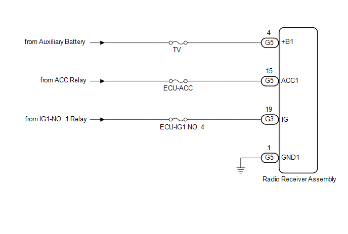
This is the power source circuit to operate the radio receiver assembly.
WIRING DIAGRAM
CAUTION / NOTICE / HINT
NOTICE:
Inspect the fuses for circuits related to this system before performing the following procedure.
PROCEDURE
| 1. | CHECK HARNESS AND CONNECTOR (RADIO RECEIVER ASSEMBLY POWER SOURCE) |
(a) Disconnect the G5 and G3 radio receiver assembly connectors.
(b) Measure the resistance according to the value(s) in the table below.
Standard Resistance:
| Tester Connection | Condition | Specified Condition |
|---|---|---|
| G5-1 (GND1) - Body ground | Always | Below 1 Ω |
(c) Measure the voltage according to the value(s) in the table below.
Standard Voltage:
| Tester Connection | Condition | Specified Condition |
|---|---|---|
| G5-4 (+B1) - G5-1 (GND1) | Power switch off | 11 to 14 V |
| G5-15 (ACC1) - G5-1 (GND1) | Power switch on (ACC) | 11 to 14 V |
| G3-19 (IG) - G5-1 (GND1) | Power switch on (IG) | 11 to 14 V |
| OK | .gif) | PROCEED TO NEXT SUSPECTED AREA SHOWN IN PROBLEM SYMPTOMS TABLE |
.gif)
| NG | | REPAIR OR REPLACE HARNESS OR CONNECTOR |
READ NEXT:
 Registered Device cannot be Deleted
PROCEDURE 1. DELETE OPERATION (a) Check if a registered portable player can be deleted normally. OK: Registered portable player can be deleted normally. OK END NG PROCEED TO
Remote Touch Screen Does not Generate Vibration Feedback
DESCRIPTION When each button displayed on the multi-display assembly is selected via remote touch screen operation, the remote touch screen generates vibration feedback according to communication betw
Reverse Signal Circuit between Radio Receiver Assembly and Navigation ECU
DESCRIPTION This circuit includes the navigation ECU and radio receiver assembly. WIRING DIAGRAM PROCEDURE 1. CHECK HARNESS AND CONNECTOR (RADIO RECEIVER ASSEMBLY - NAVIGATION ECU) (a) Disco
SEE MORE:
Extension Module Disconnected 2 (B1543)
DESCRIPTION If the radio receiver assembly cannot detect the navigation ECU for a certain period of time (90 seconds) after the power switch is turned on (ACC) and the radio receiver assembly confirms that the information is missing by checking past navigation ECU recognition information (registered
USB Device Malfunction (B1585)
DESCRIPTION This DTC is stored when a malfunction occurs in a connected device. DTC No. Detection Item DTC Detection Condition Trouble Area B1585 USB Device Malfunction When any of the following conditions is met:
A non mass-storage class or incompatible protocol USB device is co
