Lexus ES: Radio Broadcast cannot be Received or Poor Reception
CAUTION / NOTICE / HINT
NOTICE:
-
Depending on the parts that are replaced during vehicle inspection or maintenance, performing initialization, registration or calibration may be needed. Refer to Precaution for Audio and Visual System.
Click here
.gif)
-
When replacing the radio receiver assembly, always replace it with a new one. If a radio receiver assembly which was installed to another vehicle is used, the following may occur:
- A communication malfunction DTC may be stored.
- The radio receiver assembly may not operate normally.
PROCEDURE
| 1. | CHECK RADIO RECEIVER ASSEMBLY |
(a) Check the radio automatic station search function.
(1) Check the radio automatic station search function by activating it.
| Result | Proceed to |
|---|---|
| Automatic station search function does not stop. | A |
| Automatic station search function stops on a station. | B |
| B |  | REPLACE RADIO RECEIVER ASSEMBLY |
|

| 2. | CHECK OPTIONAL COMPONENTS |
(a) Check if any optional components that may decrease reception capacity, such as a sunshade film or telephone antenna, are installed.
| Result | Proceed to |
|---|---|
| Optional components are not installed. | A |
| Optional components are installed. | B |
NOTICE:
Do not remove optional components without the permission of the customer.
| B | | REMOVE OPTIONAL COMPONENTS AND CHECK AGAIN (SEE NOTICE ABOVE) |
|
| 3. | CHECK RADIO RECEIVER ASSEMBLY |
| (a) Preparation for check (1) Disconnect the antenna connector from the radio receiver assembly. |
|
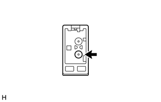
(b) Check for noise
(1) Turn the engine switch on (ACC) with the radio receiver assembly connector connected.
(2) Turn the radio on and tune into AM mode.
(3) Place a screwdriver, thin wire or other metal object on the radio receiver assembly antenna jack and check that noise can be heard from the speakers.
OK:
Noise can be heard from the speakers.
| NG | | REPLACE RADIO RECEIVER ASSEMBLY |
|
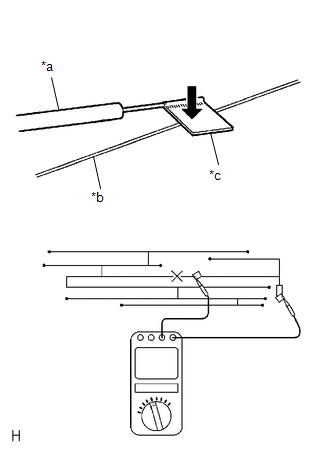
| 4. | CHECK WINDOW GLASS ANTENNA WIRE |
| (a) Check for continuity in the window glass antenna wire. NOTICE: When cleaning the glass, wipe it in the direction of the wire with a soft dry cloth. Take care not to damage the wire. Do not use detergents or glass cleaners with abrasive ingredients. When measuring resistance, wrap a piece of tin foil around the tip of each probe and press the foil against the wire with your finger, as shown in the illustration. HINT: Check for continuity at the center of each antenna wire as shown in the illustration. OK: There is continuity in the window glass antenna wire. |
|
| NG | | REPAIR WINDOW GLASS ANTENNA WIRE |
|
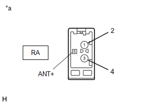
| 5. | INSPECT RADIO RECEIVER ASSEMBLY |
(a) Disconnect the RA radio receiver assembly connector.
| (b) Measure the voltage according to the value(s) in the table below. Standard Voltage:
|
|
| NG | | REPLACE RADIO RECEIVER ASSEMBLY |
|
| 6. | REPLACE ANTENNA CORD SUB-ASSEMBLY |
(a) Replace the antenna cord sub-assembly with a new or known good one and check if radio broadcasts can be received normally.
Click here
OK:
Radio broadcasts can be received normally.
| OK | | END |
|
| 7. | REPLACE NO. 2 ANTENNA CORD SUB-ASSEMBLY |
(a) Replace the No. 2 antenna cord sub-assembly with a new or known good one and check if radio broadcasts can be received normally.
Click here
OK:
Radio broadcasts can be received normally.
| OK | | END |
|
| 8. | REPLACE NO. 1 AMPLIFIER ANTENNA ASSEMBLY |
(a) Replace the No. 1 amplifier antenna assembly with a new or known good one and check if radio broadcasts can be received normally.
Click here
OK:
Radio broadcasts can be received normally.
| OK | | END |
|
| 9. | REPLACE NO. 4 ANTENNA CORD SUB-ASSEMBLY |
(a) Replace the No. 4 antenna cord sub-assembly with a new or known good one and check if radio broadcasts can be received normally.
Click here
OK:
Radio broadcasts can be received normally.
| OK | | END |
| NG | | REPLACE RADIO RECEIVER ASSEMBLY |
READ NEXT:
 Radio Receiver Power Source Circuit
DESCRIPTION This is the power source circuit to operate the radio receiver assembly. WIRING DIAGRAM CAUTION / NOTICE / HINT NOTICE: Inspect the fuses for circuits related to this system before perfor
Registered Device cannot be Deleted
PROCEDURE 1. DELETE OPERATION (a) Check if a registered portable player can be deleted normally. OK: Registered portable player can be deleted normally. OK END NG PROCEED TO
Remote Touch Screen Does not Generate Vibration Feedback
DESCRIPTION When each button displayed on the multi-display assembly is selected via remote touch screen operation, the remote touch screen generates vibration feedback according to communication betw
SEE MORE:
Dtc Check / Clear
DTC CHECK / CLEAR CHECK DTC (a) Connect the Techstream to the DLC3. (b) Turn the power switch on (IG). (c) Turn the parking support alert system on. (d) Turn the Techstream on. (e) Enter the following menus: Body Electrical / Advanced Parking Guidance/ICS/Intuitive P/A / Trouble Codes. (f) Check for
Sending Malfunction (Navigation to APGS) (U0073,U0100,U0129,U0140,U0155,U0164,U0198,U023B,U0265,U0293,U1110)
DESCRIPTION These DTCs are stored when a malfunction occurs in the CAN communication circuit. DTC No. Detection Item DTC Detection Condition Trouble Area U0073 Sending Malfunction (Navigation to APGS) CAN bus connection error CAN communication system U0100 Engine ECU Communi
