Lexus ES: Power Trunk Lid does not Operate Using Outside Switch
DESCRIPTION
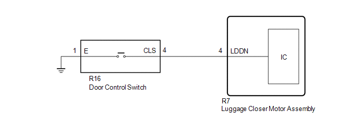
The door control switch signal is sent to the luggage closer motor assembly.
If the power trunk lid does not operate using the door control switch, a door control switch circuit malfunction is a possible cause.
WIRING DIAGRAM
CAUTION / NOTICE / HINT
NOTICE:
If the luggage closer motor assembly has been removed and installed or replaced, or if any of the connectors has been disconnected, initialize the power trunk lid system.
Click here .gif)
PROCEDURE
| 1. | READ VALUE USING TECHSTREAM |
(a) Connect the TECHSTREAM to the DLC3.
(b) Turn the engine switch on (IG).
(c) Turn the TECHSTREAM on.
(d) Enter the following menus: Body Electrical / Back Door / Data List.
(e) Read the Data List according to the display on the TECHSTREAM.
Body Electrical > Back Door > Data List| Tester Display | Measurement Item | Range | Normal Condition | Diagnostic Note |
|---|---|---|---|---|
| PBD Close SW | Door control switch signal | OFF or ON | OFF: Door control switch off ON: Door control switch on | - |
| Tester Display |
|---|
| PBD Close SW |
OK:
The Data List item changes according to the operation of the door control switch.
| OK | .gif) | REPLACE LUGGAGE CLOSER MOTOR ASSEMBLY |
|
.gif)
| 2. | INSPECT DOOR CONTROL SWITCH |
(a) Remove the door control switch.
Click here
(b) Inspect the door control switch.
Click here
| NG | | REPLACE DOOR CONTROL SWITCH |
|
| 3. | CHECK HARNESS AND CONNECTOR (DOOR CONTROL SWITCH - LUGGAGE CLOSER MOTOR ASSEMBLY) |
(a) Disconnect the R7 luggage closer motor assembly connector.
(b) Measure the resistance according to the value(s) in the table below.
| Tester Connection | Condition | Specified Condition |
|---|---|---|
| R16-4 (CSW) - R7-4 (LDDN) | Always | Below 1 Ω |
| R16-1 (E) - Body ground | Always | Below 1 Ω |
| R16-4 (CSW) or R7-4 (LDDN) - Body ground | Always | 10 kΩ or higher |
| OK | | REPLACE LUGGAGE CLOSER MOTOR ASSEMBLY |
| NG | | REPAIR OR REPLACE HARNESS OR CONNECTOR |
READ NEXT:
 Precaution
PRECAUTION PRECAUTION FOR DISCONNECTING CABLE FROM NEGATIVE AUXILIARY BATTERY TERMINAL NOTICE: When disconnecting the cable from the negative (-) auxiliary battery terminal, initialize the following s
Parts Location
PARTS LOCATION ILLUSTRATION *1 LUGGAGE DOOR OPENING CANCEL SWITCH ASSEMBLY *2 TRUNK AND FUEL SWITCH ASSEMBLY *3 LUGGAGE COMPARTMENT DOOR OPENING SWITCH *4 DLC3 *5 MAIN BODY E
SEE MORE:
DC/DC Converter Step Up Voltage Performance (P0CA300)
DTC SUMMARY MALFUNCTION DESCRIPTION This DTC indicates that it has been detected that the VH voltage cannot be boosted as commanded due to malfunction of the boost converter system. The cause of this malfunction may be one of the following: Internal inverter malfunction
Inverter with converter as
Vehicle Lift And Support Locations
VEHICLE LIFT AND SUPPORT LOCATIONS
PRECAUTIONS ABOUT VEHICLE CONDITION WHEN RAISING VEHICLE
(a) The vehicle must be unloaded before jacking up or raising the vehicle. Never
jack up or raise a heavily loaded vehicle.
(b) When removing any heavy components, like the engine, transmission, or trans
