Lexus ES: Parts Location
PARTS LOCATION
ILLUSTRATION
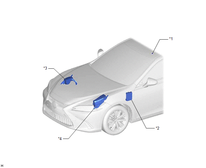
| *1 | TELEPHONE MICROPHONE ASSEMBLY | *2 | INSTRUMENT PANEL JUNCTION BLOCK ASSEMBLY - ECU-ACC FUSE - ECU-IG1 NO. 4 FUSE - ECU-IG2 NO. 3 FUSE (w/ Manual (SOS) Switch) - PANEL FUSE - ECU-DCC NO. 2 FUSE - METER-IG2 FUSE - ECU-B NO. 2 FUSE - DCM FUSE (w/ Manual (SOS) Switch) |
| *3 | NO. 2 ENGINE ROOM RELAY BLOCK AND NO. 2 JUNCTION BLOCK ASSEMBLY - AMP NO. 1 FUSE (for 17 Speakers) - AMP NO. 2 FUSE | *4 | NO. 1 ENGINE ROOM RELAY BLOCK AND NO. 1 JUNCTION BLOCK ASSEMBLY - TV FUSE |
ILLUSTRATION
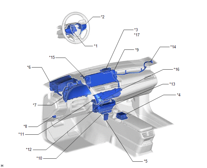
| *1 | SPIRAL CABLE SUB-ASSEMBLY | *2 | STEERING PAD SWITCH ASSEMBLY |
| *3 | NAVIGATION ANTENNA ASSEMBLY | *4 | REMOTE TOUCH (REMOTE OPERATION CONTROLLER ASSEMBLY) |
| *5 | NO. 1 STEREO JACK ADAPTER ASSEMBLY | *6 | HEADUP DISPLAY (METER MIRROR SUB ASSEMBLY) (w/ Headup Display System) |
| *7 | COMBINATION METER ASSEMBLY | *8 | DLC3 |
| *9 | MULTI-DISPLAY ASSEMBLY | *10 | DCM (TELEMATICS TRANSCEIVER) (w/ Manual (SOS) Switch) |
| *11 | NAVIGATION ECU | *12 | NO. 1 NAVIGATION WIRE |
| *13 | RADIO RECEIVER ASSEMBLY | *14 | ANTENNA CORD SUB-ASSEMBLY |
| *15 | CLOCK ASSEMBLY | *16 | AIR CONDITIONING CONTROL ASSEMBLY |
| *17 | - GPS | - | - |
ILLUSTRATION
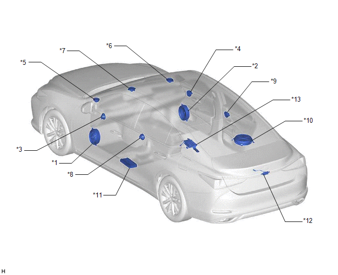
| *1 | FRONT NO. 1 SPEAKER ASSEMBLY LH | *2 | FRONT NO. 1 SPEAKER ASSEMBLY RH |
| *3 | FRONT NO. 4 SPEAKER ASSEMBLY LH (for 17 Speakers) | *4 | FRONT NO. 4 SPEAKER ASSEMBLY RH (for 17 Speakers) |
| *5 | FRONT NO. 2 SPEAKER ASSEMBLY LH | *6 | FRONT NO. 2 SPEAKER ASSEMBLY RH |
| *7 | FRONT NO. 3 SPEAKER ASSEMBLY | *8 | REAR SPEAKER ASSEMBLY LH |
| *9 | REAR SPEAKER ASSEMBLY RH | *10 | SPEAKER ASSEMBLY WITH BRACKET |
| *11 | STEREO COMPONENT AMPLIFIER ASSEMBLY | *12 | Rear Television Camera Assembly (w/ Parking Assist Monitor System) |
| *13 | Parking Assist ECU (w/ Panoramic View Monitor System) | - | - |
ILLUSTRATION
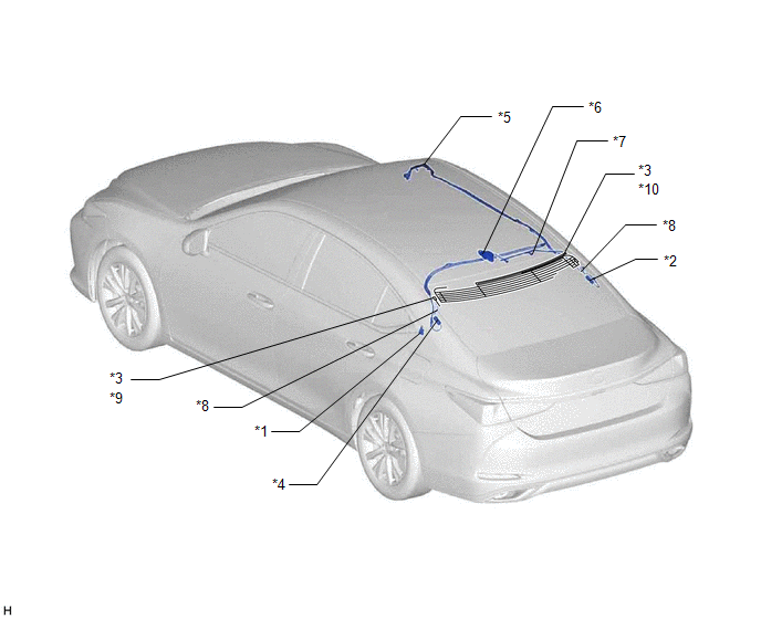
| *1 | RADIO SETTING CONDENSER | *2 | NO. 1 AMPLIFIER ANTENNA ASSEMBLY |
| *3 | WINDOW GLASS ANTENNA WIRE | *4 | NO. 2 AMPLIFIER ANTENNA ASSEMBLY |
| *5 | NO. 2 ANTENNA CORD SUB-ASSEMBLY | *6 | TELEPHONE ANTENNA ASSEMBLY - SiriusXM (w/ SXM Function) |
| *7 | NO. 3 ANTENNA CORD SUB-ASSEMBLY (w/ SXM Function) | *8 | NO. 4 ANTENNA CORD SUB-ASSEMBLY |
| *9 | - FM Sub | *10 | - FM Main - AM |
READ NEXT:
 Pointer Displayed/not Displayed Repeatedly
WIRING DIAGRAM CAUTION / NOTICE / HINT NOTICE:
Depending on the parts that are replaced during vehicle inspection or maintenance, performing initialization, registration or calibration may be need
Pointer not Displayed on Screen or Pointer does not Move
CAUTION / NOTICE / HINT NOTICE:
Depending on the parts that are replaced during vehicle inspection or maintenance, performing initialization, registration or calibration may be needed. Refer to Pre
Poor Sound Quality in All Modes (Low Volume)
PROCEDURE 1. CHECK AUDIO SETTINGS (a) Set treble, middle and bass to the initial values and check that the sound is normal. OK: The sound returns to normal. HINT: Sound quality adjustment me
SEE MORE:
Fuel Pump Ecu
ComponentsCOMPONENTS ILLUSTRATION *A w/ Silencer Sheet - - *1 FUEL PUMP CONTROL ECU *2 FUEL PUMP CONTROL ECU BRACKET *3 REAR SEAT SIDE GARNISH LH *4 REAR DOOR SCUFF PLATE LH *5 ROOM PARTITION PANEL INSULATOR *6 NO. 2 ROOM PARTITION PANEL SILENCER SHEET
Components
COMPONENTS ILLUSTRATION *A for 2WD *B for AWD *1 REAR HEIGHT CONTROL SENSOR SUB-ASSEMBLY LH - - N*m (kgf*cm, ft.*lbf): Specified torque - -
