Lexus ES: Parts Location
PARTS LOCATION
ILLUSTRATION
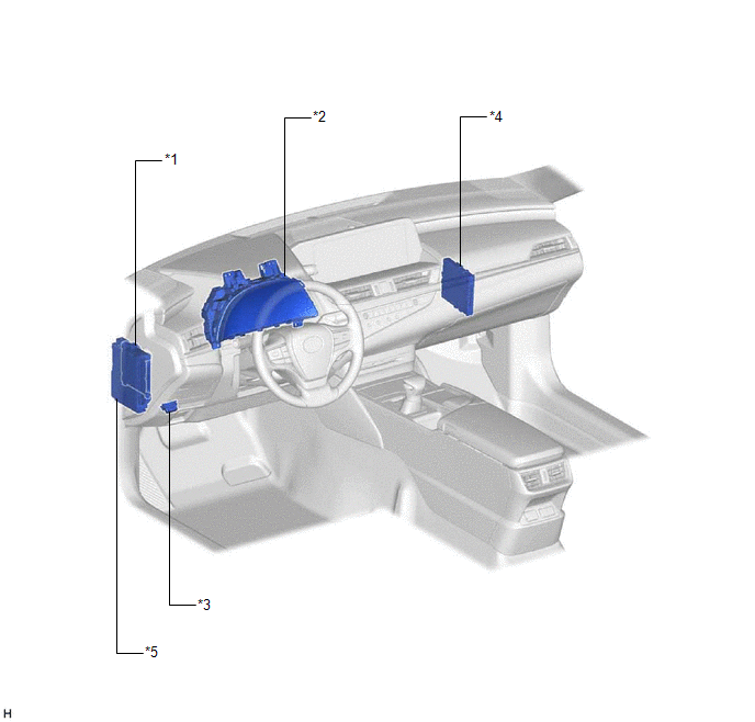
| *1 | MAIN BODY ECU (MULTIPLEX NETWORK BODY ECU) | *2 | COMBINATION METER ASSEMBLY |
| *3 | DLC3 | *4 | CERTIFICATION ECU (SMART KEY ECU ASSEMBLY) |
| *5 | INSTRUMENT PANEL JUNCTION BLOCK ASSEMBLY - ECU-B NO. 2 FUSE - DOOR F/L FUSE - DOOR F/R FUSE - DOOR R/L FUSE - DOOR R/R FUSE | - | - |
ILLUSTRATION
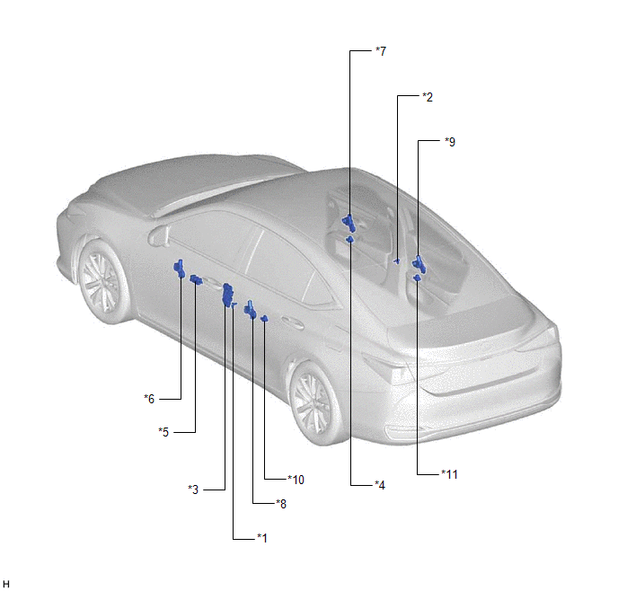
| *1 | FRONT DOOR COURTESY LIGHT SWITCH ASSEMBLY (for LH) | *2 | FRONT DOOR COURTESY LIGHT SWITCH ASSEMBLY (for RH) |
| *3 | FRONT DOOR LOCK WITH MOTOR ASSEMBLY LH | *4 | POWER WINDOW REGULATOR SWITCH ASSEMBLY |
| *5 | MULTIPLEX NETWORK MASTER SWITCH ASSEMBLY | *6 | POWER WINDOW REGULATOR MOTOR ASSEMBLY (for Driver Door) |
| *7 | POWER WINDOW REGULATOR MOTOR ASSEMBLY (for Front Passenger Door) | *8 | POWER WINDOW REGULATOR MOTOR ASSEMBLY (for Rear LH Door) |
| *9 | POWER WINDOW REGULATOR MOTOR ASSEMBLY (for Rear RH Door) | *10 | REAR POWER WINDOW REGULATOR SWITCH ASSEMBLY (for LH Door) |
| *11 | REAR POWER WINDOW REGULATOR SWITCH ASSEMBLY (for RH Door) | - | - |
READ NEXT:
 System Description
SYSTEM DESCRIPTION POWER WINDOW CONTROL SYSTEM DESCRIPTION (a) The power window control system controls the power window operation using the power window regulator motor assemblies. The main controls
System Diagram
SYSTEM DIAGRAM Communication Table Transmitting ECU Receiving ECU Signal Communication Method Multiplex Network Master Switch Assembly Power Window Regulator Motor Assembly (for Driv
How To Proceed With Troubleshooting
CAUTION / NOTICE / HINT HINT:
Use the following procedure to troubleshoot the power window control system.
*: Use the Techstream.
PROCEDURE 1. VEHICLE BROUGHT TO WORKSHOP
NEXT
SEE MORE:
How To Proceed With Troubleshooting
PROCEDURE 1. VEHICLE BROUGHT TO WORKSHOP
NEXT 2. CUSTOMER PROBLEM ANALYSIS AND SYMPTOM CHECK
NEXT 3. INSPECT AUXILIARY BATTERY VOLTAGE (a) Measure the auxiliary battery voltage with the power switch off. Standard Voltage: 11 to 14 V HINT:
Dtc Check / Clear
DTC CHECK / CLEAR CHECK DTC (a) Connect the Techstream to the DLC3. (b) Turn the engine switch on (IG). (c) Turn the Techstream on. (d) Enter the following menus: Body Electrical / Mirror L or Mirror R / Trouble Codes. Body Electrical > Mirror L > Trouble Codes Body Electrical > Mirror R &g
