Lexus ES: Parts Location
PARTS LOCATION
ILLUSTRATION
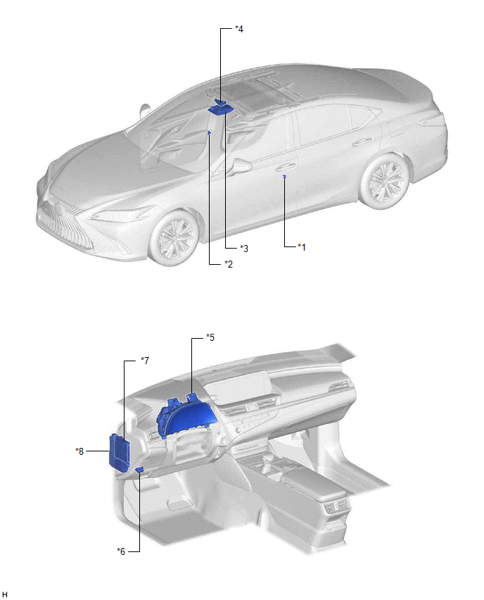
| *1 | FRONT DOOR COURTESY LIGHT SWITCH ASSEMBLY (for LH) | *2 | FRONT DOOR COURTESY LIGHT SWITCH ASSEMBLY (for RH) |
| *3 | SLIDING ROOF SWITCH (MAP LIGHT SUB-ASSEMBLY) | *4 | SLIDING ROOF ECU (SLIDING ROOF DRIVE GEAR SUB-ASSEMBLY) |
| *5 | COMBINATION METER ASSEMBLY | *6 | DLC3 |
| *7 | MAIN BODY ECU (MULTIPLEX NETWORK BODY ECU) | *8 | INSTRUMENT PANEL JUNCTION BLOCK ASSEMBLY - S/ROOF FUSE |
READ NEXT:
 System Diagram
SYSTEM DIAGRAM Communication Table Sender Receiver Signal Line Main Body ECU (Multiplex Network Body ECU) Sliding Roof ECU (Sliding Roof Drive Gear Sub-assembly)
Sliding roof oper
System Description
SYSTEM DESCRIPTION SLIDING ROOF SYSTEM DESCRIPTION (a) The sliding roof system controls the sliding roof operation using the sliding roof ECU (sliding roof drive gear sub-assembly). Operating the slid
How To Proceed With Troubleshooting
CAUTION / NOTICE / HINT HINT:
Use the following procedure to troubleshoot the sliding roof system.
*: Use the Techstream.
PROCEDURE 1. VEHICLE BROUGHT TO WORKSHOP
NEXT
SEE MORE:
Removal
REMOVAL CAUTION / NOTICE / HINT The necessary procedures (adjustment, calibration, initialization, or registration) that must be performed after parts are removed and installed, or replaced during DCM (telematics transceiver) removal/installation are shown below. Necessary Procedure After Parts Remo
Relay
On-vehicle InspectionON-VEHICLE INSPECTION PROCEDURE 1. INSPECT H-LP LH RELAY (a) Measure the resistance according to the value(s) in the table below. Standard Resistance: Tester Connection Condition Specified Condition 3 - 5 Voltage not applied between terminals 1 and 2 10 kΩ or
© 2016-2026 Copyright www.lexguide.net
