Lexus ES: System Diagram
SYSTEM DIAGRAM
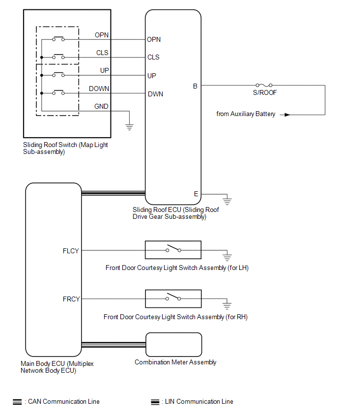 Communication Table
 | Sender | Receiver | Signal | Line |
|---|---|---|---|
| Main Body ECU (Multiplex Network Body ECU) | Sliding Roof ECU (Sliding Roof Drive Gear Sub-assembly) |
| LIN |
| Sliding Roof ECU (Sliding Roof Drive Gear Sub-assembly) | Main Body ECU (Multiplex Network Body ECU) | Sliding roof position signal | LIN |
| Combination Meter Assembly | Main Body ECU (Multiplex Network Body ECU) | Vehicle speed signal | CAN |
| Main Body ECU (Multiplex Network Body ECU) | Combination Meter Assembly | Sliding roof open warning request signal | CAN |
READ NEXT:
 System Description
SYSTEM DESCRIPTION SLIDING ROOF SYSTEM DESCRIPTION (a) The sliding roof system controls the sliding roof operation using the sliding roof ECU (sliding roof drive gear sub-assembly). Operating the slid
How To Proceed With Troubleshooting
CAUTION / NOTICE / HINT HINT:
Use the following procedure to troubleshoot the sliding roof system.
*: Use the Techstream.
PROCEDURE 1. VEHICLE BROUGHT TO WORKSHOP
NEXT
Operation Check
OPERATION CHECK CHECK AUTO OPERATION FUNCTION NOTICE:
Make sure that initialization has been completed before performing this inspection.
Click here
The sliding roof auto operation can be custo
SEE MORE:
Driving position memory
This feature automatically adjusts
the positions of the driver's seat,
steering wheel (power adjustment
type), outside rear view mirrors and
head-up display (if equipped) to
make entering and exiting the vehicle
easier or to suit your preferences.
Up to 3 different driving positions
can be
Terminals Of Ecu
TERMINALS OF ECU STEREO COMPONENT EQUALIZER ASSEMBLY Terminal No. (Symbol) Wiring Color Terminal Description Condition Specified Condition G15-1 (CANH) P CAN communication signal - - G15-2 (ACK1) V Serial communication (UART) signal - - G15-3 (NEI) - G15-28 (G
© 2016-2026 Copyright www.lexguide.net
