Lexus ES: Data Signal Circuit between Radio Receiver and Stereo Jack Adapter
DESCRIPTION
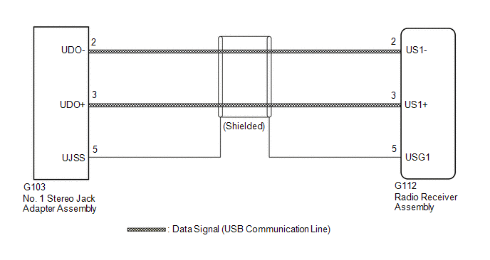
The No. 1 stereo jack adapter assembly sends the sound data signal or image data signal from a USB device to the radio receiver assembly via this circuit.
WIRING DIAGRAM

PROCEDURE
| 1. | CHECK HARNESS AND CONNECTOR (RADIO RECEIVER ASSEMBLY - NO. 1 STEREO JACK ADAPTER ASSEMBLY) |
(a) Disconnect the G112 radio receiver assembly connector.
(b) Disconnect the G103 No. 1 stereo jack adapter assembly connector.
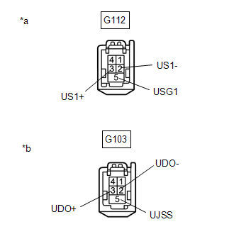
| (c) Measure the resistance according to the value(s) in the table below. Standard Resistance: | Tester Connection | Condition | Specified Condition | | G112-2 (US1-) - G103-2 (UDO-) | Always | Below 1 Ω | | G112-3 (US1+) - G103-3 (UDO+) | Always | Below 1 Ω | | G112-5 (USG1) - G103-5 (UJSS) | Always | Below 1 Ω | | G112-2 (US1-) or G103-2 (UDO-) - Body ground | Always | 10 kΩ or higher | | G112-3 (US1+) or G103-3 (UDO+) - Body ground | Always | 10 kΩ or higher | | G112-5 (USG1) or G103-5 (UJSS) - Body ground | Always | 10 kΩ or higher | |  | | *a | Front view of wire harness connector (to Radio Receiver Assembly) | | *b | Front view of wire harness connector (to No. 1 Stereo Jack Adapter Assembly) | | |
| NG |  | REPAIR OR REPLACE HARNESS OR CONNECTOR |
READ NEXT:
DIAGNOSTIC TROUBLE CODE CHART Audio and Visual System DTC No. Detection Item Link B1323 Lost Communication with Haptic Device B1324 Lost Communication with Meter B1326
DESCRIPTION When the audio and visual system is activated with the light control switch in the tail or head position, before AVC-LAN communication is established, the multi-display assembly dims the d
CAUTION / NOTICE / HINT NOTICE:
Depending on the parts that are replaced during vehicle inspection or maintenance, performing initialization, registration or calibration may be needed. Refer to Pre
SEE MORE:
CUSTOMIZE PARAMETERS CUSTOMIZING WITH REMOTE TOUCH (a) Customizing with the touch function cancellation function. (w/ Touch Function Cancellation Function) NOTICE: Confirm the touchpad surface is free of foreign matter before customizing. (1) Turn the engine switch on (ACC). (2) Simultaneously press
REASSEMBLY PROCEDURE 1. INSTALL FUEL PUMP WITH FILTER ASSEMBLY HINT: Perform "Inspection After Repair" after replacing the fuel pump with filter assembly. Click here (a) Apply gasoline to a new O-ring. Then install the O-ring and fuel pump spacer to the fuel pump. *1 O-ring
© 2016-2025 Copyright www.lexguide.net


.gif)
