
Lexus ES: Parts Location
PARTS LOCATION
ILLUSTRATION
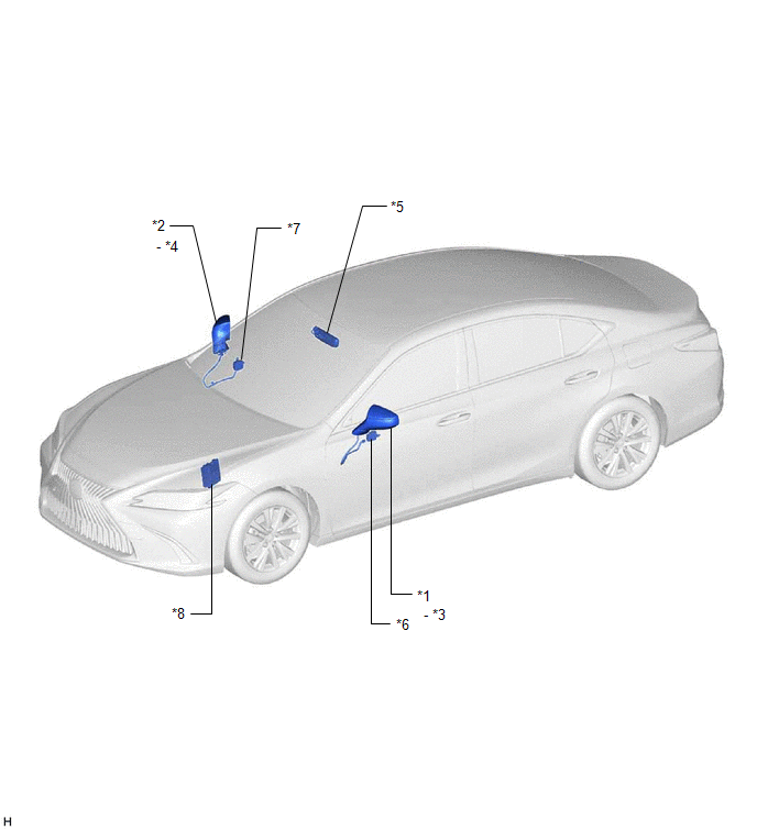
| *1 | OUTER REAR VIEW MIRROR ASSEMBLY (DRIVER DOOR) | *2 | OUTER REAR VIEW MIRROR ASSEMBLY (FRONT PASSENGER DOOR) |
| *3 | OUTER MIRROR (DRIVER DOOR) | *4 | OUTER MIRROR (FRONT PASSENGER DOOR) |
| *5 | INNER REAR VIEW MIRROR ASSEMBLY | *6 | OUTER MIRROR CONTROL ECU ASSEMBLY (DRIVER DOOR) |
| *7 | OUTER MIRROR CONTROL ECU ASSEMBLY (FRONT PASSENGER DOOR) | *8 | ECM |
ILLUSTRATION
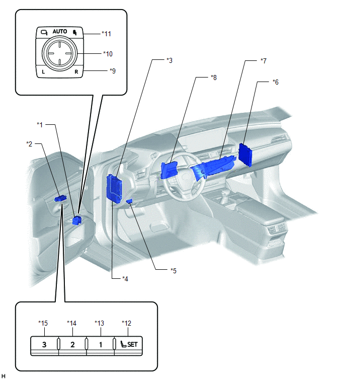
| *1 | OUTER MIRROR SWITCH ASSEMBLY | *2 | SEAT MEMORY SWITCH |
| *3 | MAIN BODY ECU (MULTIPLEX NETWORK BODY ECU) | *4 | INSTRUMENT PANEL JUNCTION BLOCK ASSEMBLY - DOOR F/R FUSE - DOOR F/L FUSE - ECU-IG1 NO. 4 FUSE - ECU-DCC NO. 2 FUSE |
| *5 | DLC3 | *6 | CERTIFICATION ECU (SMART KEY ECU ASSEMBLY) |
| *7 | REAR WINDOW DEFOGGER SWITCH (AIR CONDITIONING CONTROL ASSEMBLY) | *8 | AIR CONDITIONING AMPLIFIER ASSEMBLY |
| *9 | MIRROR SELECT SWITCH | *10 | MIRROR ADJUST SWITCH |
| *11 | RETRACTABLE OUTER MIRROR SWITCH | *12 | SET SWITCH |
| *13 | M1 SWITCH | *14 | M2 SWITCH |
| *15 | M3 SWITCH | - | - |
READ NEXT:
 System Description
SYSTEM DESCRIPTION POWER MIRROR CONTROL SYSTEM (w/ Memory) DESCRIPTION (a) This system has the following functions: electrical remote control mirror function, memory and reactivation function, power r
System Diagram
SYSTEM DIAGRAM Communication Table Sender Receiver Signal Line Main Body ECU (Multiplex Network Body ECU) Outer Mirror Control ECU Assembly
IG signal
ACC signal
Outer mirror
How To Proceed With Troubleshooting
CAUTION / NOTICE / HINT HINT:
Use the following procedure to troubleshoot the power mirror control system (w/ Memory).
*: Use the Techstream.
PROCEDURE 1. VEHICLE BROUGHT TO WORKSHOP
SEE MORE:
Removal
REMOVAL CAUTION / NOTICE / HINT The necessary procedures (adjustment, calibration, initialization or registration) that must be performed after parts are removed and installed, or replaced during engine assembly removal/installation are shown below. Necessary Procedure After Parts Removed/Installed/
Components
COMPONENTS ILLUSTRATION *A for TMK Made *B for TMMK Made *1 ACCELERATOR PEDAL ASSEMBLY *2 ACCELERATOR PEDAL PAD *3 ACCELERATOR PEDAL SENSOR ASSEMBLY *4 NO. 1 INSTRUMENT PANEL UNDER COVER SUB-ASSEMBLY Tightening torque for "Major areas involving basic vehicle perf
