Lexus ES: System Diagram
SYSTEM DIAGRAM
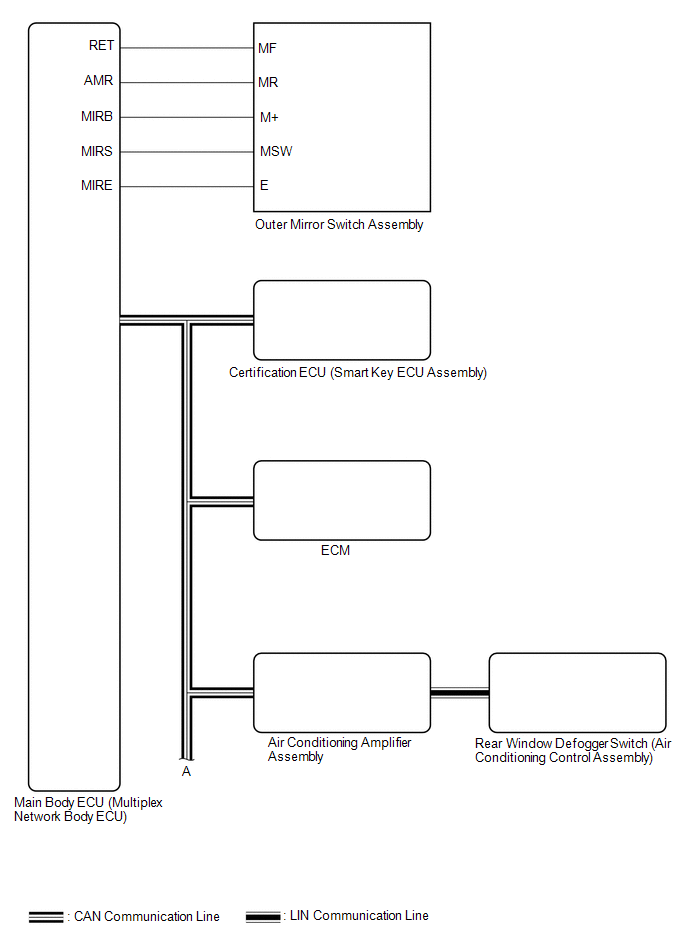
 Communication Table
 | Sender | Receiver | Signal | Line |
|---|---|---|---|
| Main Body ECU (Multiplex Network Body ECU) | Outer Mirror Control ECU Assembly |
| CAN |
| Outer Mirror Control ECU Assembly | Main Body ECU (Multiplex Network Body ECU) |
| CAN |
| Certification ECU (Smart Key ECU Assembly) | Main Body ECU (Multiplex Network Body ECU) | Key ID signal | CAN |
| Air Conditioning Amplifier Assembly | Outer Mirror Control ECU Assembly | Mirror heater drive request signal | CAN |
| ECM | Main Body ECU (Multiplex Network Body ECU) | Reverse signal | CAN |
| Rear Window Defogger switch (Air Conditioning Control Assembly) | Air Conditioning Amplifier Assembly | Mirror heater switch (rear window defogger switch) operation signal | LIN |
READ NEXT:
 How To Proceed With Troubleshooting
CAUTION / NOTICE / HINT HINT:
Use the following procedure to troubleshoot the power mirror control system (w/ Memory).
*: Use the Techstream.
PROCEDURE 1. VEHICLE BROUGHT TO WORKSHOP
Customize Parameters
CUSTOMIZE PARAMETERS CUSTOMIZE POWER MIRROR CONTROL SYSTEM (w/ Memory) NOTICE:
When the customer requests a change in a function, first make sure that the function can be customized.
Record the c
Operation Check
OPERATION CHECK CHECK ELECTRICAL REMOTE CONTROL MIRROR FUNCTION (a) Turn the engine switch on (IG). (b) b. With the mirror select switch driver side switch on, check that the outer rear view mirror as
SEE MORE:
Brake Hold Standby Indicator Light Circuit
DESCRIPTION The brake hold standby indicator light turns on if brake hold control is possible when the following conditions required for operation standby are met and the brake hold switch (No. 3 combination switch assembly) is pressed while the engine switch on (IG).
Conditions required for oper
On-vehicle Inspection
ON-VEHICLE INSPECTION PROCEDURE 1. INSPECT MASS AIR FLOW METER SUB-ASSEMBLY HINT: Perform "Inspection After Repair" after replacing the mass air flow meter sub-assembly. Click here (a) Read the value of Data List item "Mass Air Flow Sensor" using the Techstream. NOTICE: Perform the inspection of t
© 2016-2026 Copyright www.lexguide.net
