Lexus ES: Parts Location
PARTS LOCATION
ILLUSTRATION
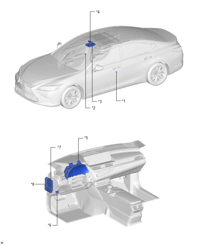
| *1 | FRONT DOOR COURTESY LIGHT SWITCH ASSEMBLY (for LH) | *2 | FRONT DOOR COURTESY LIGHT SWITCH ASSEMBLY (for RH) |
| *3 | SLIDING ROOF SWITCH (MAP LIGHT SUB-ASSEMBLY) | *4 | SLIDING ROOF ECU (SLIDING ROOF DRIVE GEAR SUB-ASSEMBLY) |
| *5 | COMBINATION METER ASSEMBLY | *6 | DLC3 |
| *7 | MAIN BODY ECU (MULTIPLEX NETWORK BODY ECU) | *8 | INSTRUMENT PANEL JUNCTION BLOCK ASSEMBLY - S/ROOF FUSE |
READ NEXT:
 System Diagram
SYSTEM DIAGRAM Communication Table Sender Receiver Signal Line Main Body ECU (Multiplex Network Body ECU) Sliding Roof ECU (Sliding Roof Drive Gear Sub-assembly)
Sliding roof oper
System Description
SYSTEM DESCRIPTION SLIDING ROOF SYSTEM DESCRIPTION (a) The sliding roof system controls the sliding roof operation using the sliding roof ECU (sliding roof drive gear sub-assembly). Operating the slid
How To Proceed With Troubleshooting
CAUTION / NOTICE / HINT HINT:
Use the following procedure to troubleshoot the sliding roof system.
*: Use the Techstream.
PROCEDURE 1. VEHICLE BROUGHT TO WORKSHOP
NEXT
SEE MORE:
Front Left Center Sensor (C1AE2)
DESCRIPTION The front center ultrasonic sensor LH is installed to the front bumper. The clearance warning ECU assembly detects obstacles based on signals received from the front center ultrasonic sensor LH. If the front center ultrasonic sensor LH has an open circuit or other malfunction, it will no
Actuator Malfunction (C13A7)
DESCRIPTION DTC No. Detection Item DTC Detection Condition Trouble Area Memory Note C13A7 Actuator Malfunction Both of following conditions are met:
Electric parking brake is operating
One of following is detected: Motor lock, gear lock, motor spinning or repeated slipping
© 2016-2026 Copyright www.lexguide.net
