Lexus ES: Parts Location
Lexus ES (XZ10) Service Manual / Steering / Power Assist Systems / Power Steering System(for Gasoline Model) / Parts Location
PARTS LOCATION
ILLUSTRATION
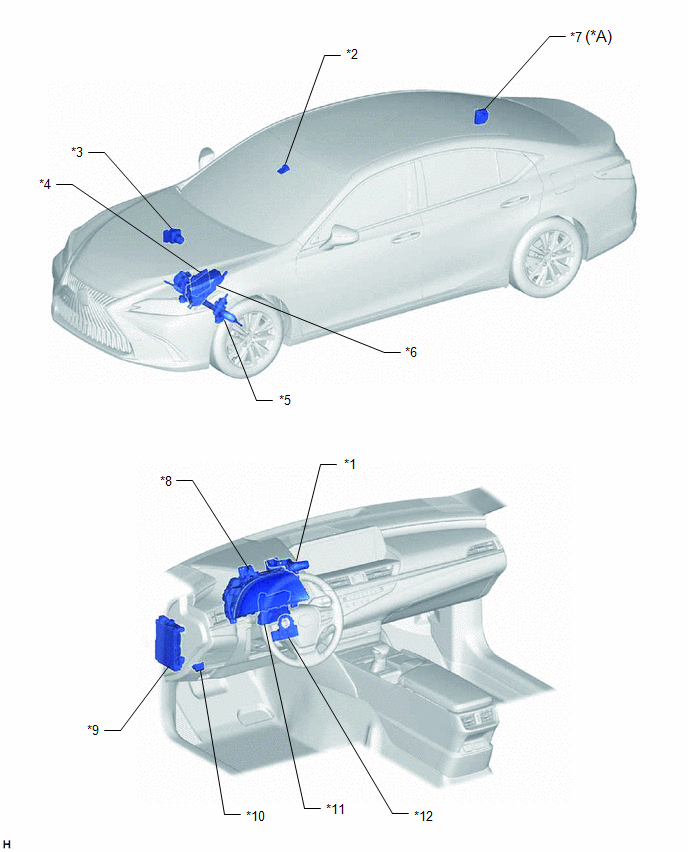
| *A | w/ Adaptive Variable Suspension System | - | - |
| *1 | DRIVE MODE SELECT SWITCH (COMBINATION SWITCH ASSEMBLY) | *2 | FORWARD RECOGNITION CAMERA |
| *3 | BRAKE ACTUATOR ASSEMBLY - SKID CONTROL ECU | *4 | ECM |
| *5 | RACK AND PINION POWER STEERING GEAR ASSEMBLY - POWER STEERING ECU -POWER STEERING MOTOR -TORQUE SENSOR | *6 | NO. 1 ENGINE ROOM RELAY BLOCK AND NO. 1 JUNCTION BLOCK - EPS FUSE |
| *7 | AVS ECU (ABSORBER CONTROL ECU) | *8 | COMBINATION METER ASSEMBLY |
| *9 | INSTRUMENT PANEL JUNCTION BLOCK ASSEMBLY - IG1-NO. 1 RELAY - EPS-IG1 FUSE | *10 | DLC3 |
| *11 | AIR CONDITIONING AMPLIFIER ASSEMBLY | *12 | STEERING SENSOR |
READ NEXT:
 System Diagram
SYSTEM DIAGRAM
System Diagram
SYSTEM DIAGRAM
System Description
SYSTEM DESCRIPTION DESCRIPTION (a) The power steering ECU (rack and pinion power steering gear assembly) generates the necessary steering assist torque by calculating the steering assist force and con
SEE MORE:
Removal
REMOVAL CAUTION / NOTICE / HINT HINT:
Use the same procedure for the RH side and LH side.
The following procedure is for the LH side.
PROCEDURE 1. REMOVE NO. 2 DOOR TRIM PAD Click here 2. REMOVE MULTIPLEX NETWORK MASTER SWITCH ASSEMBLY WITH FRONT DOOR UPPER ARMREST BASE PANEL (for Driver
Installation
INSTALLATION PROCEDURE 1. INSTALL TILT AND TELESCOPIC SWITCH (a) Engage the claw to install the tilt and telescopic switch. (b) Connect the tilt and telescopic connector to the tilt and telescopic switch. (c) Connect the spiral cable connector to the spiral cable sub-assembly. 2. CONNECT CABLE TO NE
© 2016-2026 Copyright www.lexguide.net
