Lexus ES: Parts Location
PARTS LOCATION
ILLUSTRATION
.png)
| *1 | TELEPHONE MICROPHONE ASSEMBLY | *2 | INSTRUMENT PANEL JUNCTION BLOCK ASSEMBLY - ECU-ACC FUSE - ECU-IG1 NO. 4 FUSE - PANEL FUSE - METER-IG2 FUSE - ECU-IG2 NO. 3 FUSE (w/ Manual (SOS) Switch) - ECU-B NO. 2 FUSE - DCM FUSE (w/ Manual (SOS) Switch) - ECU-DCC NO. 2 FUSE |
| *3 | NO. 1 ENGINE ROOM RELAY BLOCK AND NO. 1 JUNCTION BLOCK ASSEMBLY - TV FUSE | *4 | NO. 2 ENGINE ROOM RELAY BLOCK AND NO. 2 JUNCTION BLOCK ASSEMBLY - AMP NO. 1 FUSE (for 17 Speakers) - AMP NO. 2 FUSE |
ILLUSTRATION
.png)
| *1 | SPIRAL CABLE SUB-ASSEMBLY | *2 | STEERING PAD SWITCH ASSEMBLY |
| *3 | RADIO RECEIVER ASSEMBLY | *4 | REMOTE TOUCH (REMOTE OPERATION CONTROLLER ASSEMBLY) |
| *5 | NO. 1 STEREO JACK ADAPTER ASSEMBLY | *6 | CLOCK ASSEMBLY |
| *7 | COMBINATION METER ASSEMBLY | *8 | DLC3 |
| *9 | MULTI-DISPLAY ASSEMBLY | *10 | DCM (TELEMATICS TRANSCEIVER) (w/ Manual (SOS) Switch) |
| *11 | NAVIGATION ANTENNA ASSEMBLY | *12 | ANTENNA CORD SUB-ASSEMBLY |
| *13 | AIR CONDITIONING CONTROL ASSEMBLY | *14 | - GPS |
ILLUSTRATION

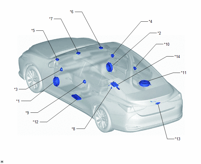
| *1 | FRONT NO. 1 SPEAKER ASSEMBLY LH | *2 | FRONT NO. 1 SPEAKER ASSEMBLY RH |
| *3 | FRONT NO. 4 SPEAKER ASSEMBLY LH (for 17 Speakers) | *4 | FRONT NO. 4 SPEAKER ASSEMBLY RH (for 17 Speakers) |
| *5 | FRONT NO. 2 SPEAKER ASSEMBLY LH | *6 | FRONT NO. 2 SPEAKER ASSEMBLY RH |
| *7 | FRONT NO. 3 SPEAKER ASSEMBLY | *8 | RADIO SETTING CONDENSER |
| *9 | REAR SPEAKER ASSEMBLY LH | *10 | REAR SPEAKER ASSEMBLY RH |
| *11 | SPEAKER ASSEMBLY WITH BRACKET | *12 | STEREO COMPONENT AMPLIFIER ASSEMBLY |
| *13 | REAR TELEVISION CAMERA ASSEMBLY (w/ Parking Assist Monitor System) | *14 | PARKING ASSIST ECU (w/ Panoramic View Monitor System) |
ILLUSTRATION

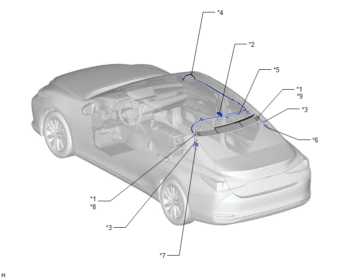
| *1 | WINDOW GLASS ANTENNA WIRE | *2 | TELEPHONE ANTENNA ASSEMBLY - SiriusXM (w/ SXM Function) |
| *3 | NO. 4 ANTENNA CORD SUB-ASSEMBLY | *4 | NO. 2 ANTENNA CORD SUB-ASSEMBLY |
| *5 | NO. 3 ANTENNA CORD SUB-ASSEMBLY (w/ SXM Function) | *6 | NO. 1 AMPLIFIER ANTENNA ASSEMBLY |
| *7 | NO. 2 AMPLIFIER ANTENNA ASSEMBLY | *8 | - FM SUB |
| *9 | - FM MAIN - AM | - | - |

