Lexus ES: Parts Location
Lexus ES (XZ10) Service Manual / Engine & Hybrid System / Cruise Control / Road Sign Assist System (for Hv Model) / Parts Location
PARTS LOCATION
ILLUSTRATION
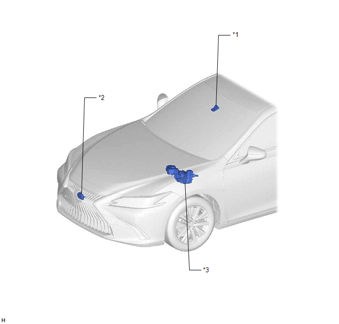
| *1 | FORWARD RECOGNITION CAMERA | *2 | MILLIMETER WAVE RADAR SENSOR ASSEMBLY |
| *3 | BRAKE BOOSTER WITH MASTER CYLINDER ASSEMBLY - SKID CONTROL ECU | - | - |
ILLUSTRATION
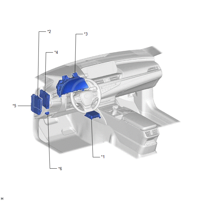
| *1 | AIRBAG ECU ASSEMBLY - YAW RATE SENSOR | *2 | MAIN BODY ECU (MULTIPLEX NETWORK BODY ECU) |
| *3 | COMBINATION METER ASSEMBLY | *4 | HYBRID VEHICLE CONTROL ECU |
| *5 | INSTRUMENT PANEL JUNCTION BLOCK ASSEMBLY - ECU-IG1 NO. 3 FUSE | *6 | DLC3 |
READ NEXT:
 System Diagram
SYSTEM DIAGRAM
How To Proceed With Troubleshooting
CAUTION / NOTICE / HINT HINT:
Before performing troubleshooting for the road sign assist system, make sure that the pre-collision system and lane control system are not malfunctioning.
Pre-collisio
Customize Parameters
CUSTOMIZE PARAMETERS CUSTOMIZE ROAD SIGN ASSIST SYSTEM NOTICE: Be sure to make a note of the current settings before customizing. (a) Customizing with the multi-information display (1) Turn the power
SEE MORE:
Data List / Active Test
DATA LIST / ACTIVE TEST DATA LIST HINT: Using the Techstream to read the Data List allows the values or states of switches, sensors, actuators and other items to be read without removing any parts. This non-intrusive inspection can be very useful because intermittent conditions or signals may be dis
Components
COMPONENTS ILLUSTRATION *1 LOWER STEERING COLUMN COVER SUB-ASSEMBLY *2 TURN SIGNAL SWITCH *3 UPPER STEERING COLUMN COVER - -
© 2016-2026 Copyright www.lexguide.net
