Lexus ES: System Diagram
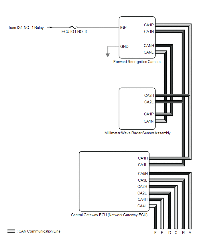
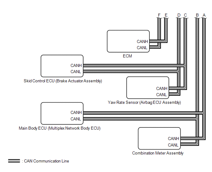
SYSTEM DIAGRAM
READ NEXT:
 Customize Parameters
CUSTOMIZE PARAMETERS CUSTOMIZE ROAD SIGN ASSIST SYSTEM NOTICE: Be sure to make a note of the current settings before customizing. (a) Customizing with the multi-information display (1) Turn the engine
How To Proceed With Troubleshooting
CAUTION / NOTICE / HINT HINT:
Before performing troubleshooting for the road sign assist system, make sure that the pre-collision system and lane control system are not malfunctioning.
Pre-collisio
Utility
UTILITY NOTICE: If the forward recognition camera has been replaced due to a malfunction in the road sign assist system, be sure to perform forward recognition camera adjustment. Otherwise all systems
SEE MORE:
Operation Check
OPERATION CHECK CHECK ELECTRICAL REMOTE CONTROL MIRROR FUNCTION (a) Turn the power switch on (IG). (b) b. With the mirror select switch driver side switch on, check that the outer rear view mirror assembly (driver door) surface moves up, down, left and right normally (c) With the mirror select switc
Terminals Of Ecu
TERMINALS OF ECU CHECK INSTRUMENT PANEL JUNCTION BLOCK ASSEMBLY AND MAIN BODY ECU (MULTIPLEX NETWORK BODY ECU) (a) Remove the main body ECU (multiplex network body ECU) from the instrument panel junction block assembly. Click here (b) Measure the resistance according to the value(s) in the table
© 2016-2026 Copyright www.lexguide.net
