Lexus ES: Parts Location
PARTS LOCATION
ILLUSTRATION
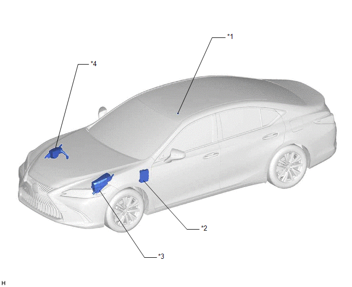
| *1 | TELEPHONE MICROPHONE ASSEMBLY | *2 | INSTRUMENT PANEL JUNCTION BLOCK ASSEMBLY - ECU-ACC FUSE - ECU-IG1 NO. 4 FUSE - PANEL FUSE - METER-IG2 FUSE - ECU-IG2 NO. 3 FUSE (w/ Manual (SOS) Switch) - ECU-B NO. 2 FUSE - DCM FUSE (w/ Manual (SOS) Switch) - ECU-DCC NO. 2 FUSE |
| *3 | NO. 1 ENGINE ROOM RELAY BLOCK AND NO. 1 JUNCTION BLOCK ASSEMBLY - TV FUSE | *4 | NO. 2 ENGINE ROOM RELAY BLOCK AND NO. 2 JUNCTION BLOCK ASSEMBLY - AMP NO. 1 FUSE (for 17 Speakers) - AMP NO. 2 FUSE |
ILLUSTRATION
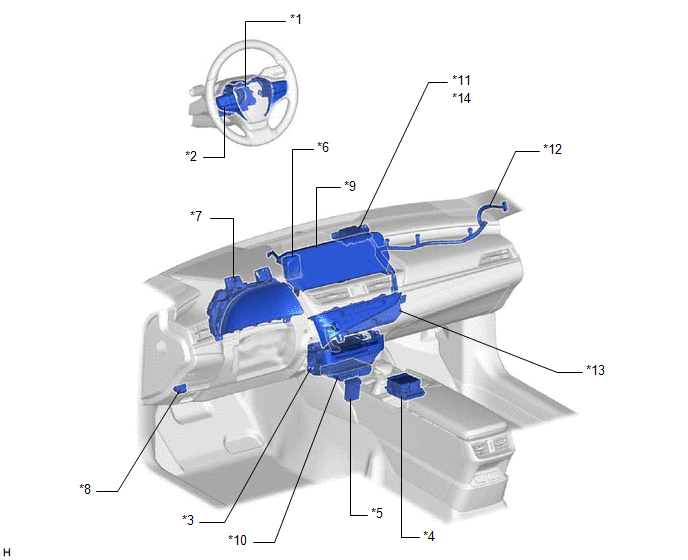
| *1 | SPIRAL CABLE SUB-ASSEMBLY | *2 | STEERING PAD SWITCH ASSEMBLY |
| *3 | RADIO RECEIVER ASSEMBLY | *4 | REMOTE TOUCH (REMOTE OPERATION CONTROLLER ASSEMBLY) |
| *5 | NO. 1 STEREO JACK ADAPTER ASSEMBLY | *6 | CLOCK ASSEMBLY |
| *7 | COMBINATION METER ASSEMBLY | *8 | DLC3 |
| *9 | MULTI-DISPLAY ASSEMBLY | *10 | DCM (TELEMATICS TRANSCEIVER) (w/ Manual (SOS) Switch) |
| *11 | NAVIGATION ANTENNA ASSEMBLY | *12 | ANTENNA CORD SUB-ASSEMBLY |
| *13 | AIR CONDITIONING CONTROL ASSEMBLY | *14 | - GPS |
ILLUSTRATION
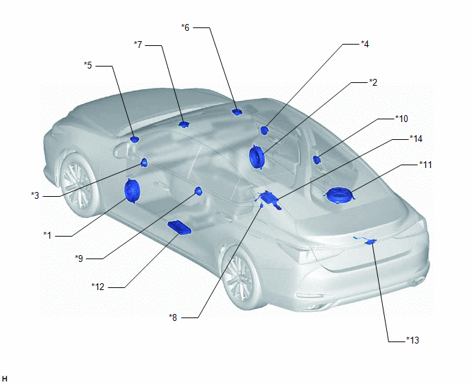
| *1 | FRONT NO. 1 SPEAKER ASSEMBLY LH | *2 | FRONT NO. 1 SPEAKER ASSEMBLY RH |
| *3 | FRONT NO. 4 SPEAKER ASSEMBLY LH (for 17 Speakers) | *4 | FRONT NO. 4 SPEAKER ASSEMBLY RH (for 17 Speakers) |
| *5 | FRONT NO. 2 SPEAKER ASSEMBLY LH | *6 | FRONT NO. 2 SPEAKER ASSEMBLY RH |
| *7 | FRONT NO. 3 SPEAKER ASSEMBLY | *8 | RADIO SETTING CONDENSER |
| *9 | REAR SPEAKER ASSEMBLY LH | *10 | REAR SPEAKER ASSEMBLY RH |
| *11 | SPEAKER ASSEMBLY WITH BRACKET | *12 | STEREO COMPONENT AMPLIFIER ASSEMBLY |
| *13 | REAR TELEVISION CAMERA ASSEMBLY (w/ Parking Assist Monitor System) | *14 | PARKING ASSIST ECU (w/ Panoramic View Monitor System) |
ILLUSTRATION
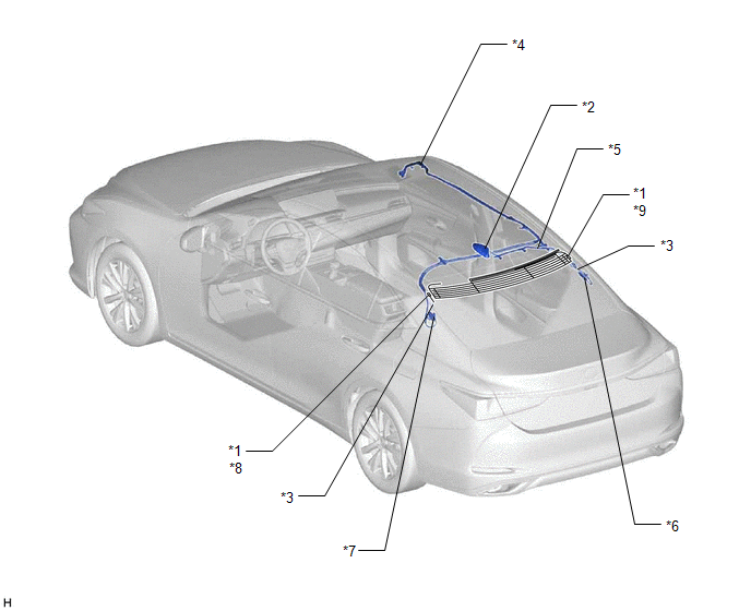
| *1 | WINDOW GLASS ANTENNA WIRE | *2 | TELEPHONE ANTENNA ASSEMBLY - SiriusXM (w/ SXM Function) |
| *3 | NO. 4 ANTENNA CORD SUB-ASSEMBLY | *4 | NO. 2 ANTENNA CORD SUB-ASSEMBLY |
| *5 | NO. 3 ANTENNA CORD SUB-ASSEMBLY (w/ SXM Function) | *6 | NO. 1 AMPLIFIER ANTENNA ASSEMBLY |
| *7 | NO. 2 AMPLIFIER ANTENNA ASSEMBLY | *8 | - FM SUB |
| *9 | - FM MAIN - AM | - | - |
READ NEXT:
 Pointer Displayed/not Displayed Repeatedly
WIRING DIAGRAM CAUTION / NOTICE / HINT NOTICE:
Depending on the parts that are replaced during vehicle inspection or maintenance, performing initialization, registration or calibration may be need
Pointer not Displayed on Screen or Pointer does not Move
CAUTION / NOTICE / HINT NOTICE:
Depending on the parts that are replaced during vehicle inspection or maintenance, performing initialization, registration or calibration may be needed. Refer to Pre
Poor Sound Quality in All Modes (Low Volume)
PROCEDURE 1. CHECK AUDIO SETTINGS (a) Set treble, middle and bass to the initial values and check that the sound is normal. OK: The sound returns to normal. HINT: Sound quality adjustment me
SEE MORE:
Auto Down Operation does not Fully Open Power Window (Catch Protection Function is Activated)
DESCRIPTION If a door glass does not slide smoothly or a power window regulator motor assembly or door window regulator sub-assembly does not operate smoothly, the catch protection function may be triggered automatically, resulting in the auto down operation being unable to fully open the power wind
Diagnostic Trouble Code Chart
DIAGNOSTIC TROUBLE CODE CHART Panoramic Moon Roof System DTC No. Detection Item Link B2341 Sensor (Motor) Failure B2342 Switch Failure B2343 Position Initialization Incomplete B2344 Position Failure B2345 Motor Control Relay Stuck ON
