Lexus ES: Parts Location
PARTS LOCATION
ILLUSTRATION
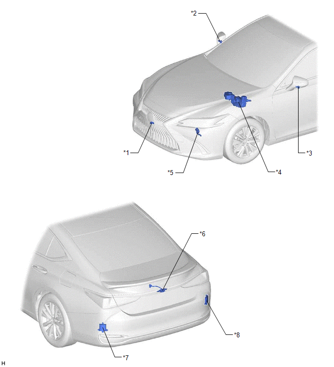
| *1 | FRONT TELEVISION CAMERA ASSEMBLY | *2 | SIDE TELEVISION CAMERA ASSEMBLY RH |
| *3 | SIDE TELEVISION CAMERA ASSEMBLY LH | *4 | BRAKE BOOSTER WITH MASTER CYLINDER ASSEMBLY - SKID CONTROL ECU |
| *5 | SHIFT LEVER POSITION SENSOR | *6 | REAR TELEVISION CAMERA ASSEMBLY |
| *7 | BLIND SPOT MONITOR SENSOR LH | *8 | BLIND SPOT MONITOR SENSOR RH |
| *9 | OUTER REAR VIEW MIRROR ASSEMBLY LH | *10 | OUTER REAR VIEW MIRROR ASSEMBLY RH |
ILLUSTRATION
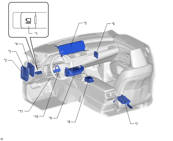
| *1 | PANORAMIC VIEW MONITOR SWITCH (NO. 2 COMBINATION SWITCH ASSEMBLY) | *2 | INSTRUMENT PANEL JUNCTION BLOCK ASSEMBLY - ECU-IG1 NO. 3 FUSE - ECU-DCC NO. 1 FUSE - ECU-ACC FUSE - BKUP LP Relay |
| *3 | MAIN BODY ECU (MULTIPLEX NETWORK BODY ECU) | *4 | HYBRID VEHICLE CONTROL ECU |
| *5 | MULTI-DISPLAY ASSEMBLY | *6 | CLEARANCE WARNING ECU ASSEMBLY |
| *7 | PARKING ASSIST ECU | *8 | REMOTE TOUCH (REMOTE OPERATION CONTROLLER ASSEMBLY) |
| *9 | RADIO RECEIVER ASSEMBLY | *10 | STEERING SENSOR |
| *11 | DLC3 | - | - |
READ NEXT:
 Precaution
PRECAUTION PRECAUTION FOR DISCONNECTING CABLE FROM NEGATIVE AUXILIARY BATTERY TERMINAL NOTICE: When disconnecting the cable from the negative (-) auxiliary battery terminal, initialize the following s
Problem Symptoms Table
PROBLEM SYMPTOMS TABLE NOTICE:
The following inspection procedure of the panoramic view monitor system is described on the assumption that the audio and visual system*1 or navigation system*2 is no
System Description
SYSTEM DESCRIPTION GENERAL (a) This system has front, passenger side, driver side and rear television camera assemblies mounted around the vehicle to display around the vehicle on the multi-display as
SEE MORE:
Lost Communication with Multi-axis Acceleration Sensor Module Missing Message (U012587,U012987,U014087,U029387)
DESCRIPTION These DTCs are stored if a CAN communication malfunction occurs between the forward recognition camera and other ECUs. DTC No. Detection Item DTC Detection Condition Trouble Area DTC Output from U012587 Lost Communication with Multi-axis Acceleration Sensor Module Missin
Terminals Of Ecu
TERMINALS OF ECU *1 Battery ECU assembly - - Terminal No. (Symbols) Wiring Color Input/Output Terminal Description Condition Specified Condition y16-1 (AM) - y16-27 (GND) BR - W-G IN Constant power source Always 11 to 14 V y16-27 (GND) - Body ground W-G
