Lexus ES: Crankshaft Position - Camshaft Position Correlation Bank 1 Sensor A (P001600,P001800)
DESCRIPTION
In the VVT (Variable Valve Timing) system, the appropriate intake valve open and close timing is controlled by the ECM. The ECM performs intake valve control by performing the following: 1) controlling the intake camshaft, cam timing oil control solenoid assembly, camshaft timing gear bolt (camshaft timing oil control valve assembly [for intake camshaft]) and operating the camshaft timing gear; and 2) changing the relative positions of the camshaft and crankshaft.
| DTC No. | Detection Item | DTC Detection Condition | Trouble Area | MIL | Memory | Note |
|---|---|---|---|---|---|---|
| P001600 | Crankshaft Position - Camshaft Position Correlation Bank 1 Sensor A | Deviation in the crankshaft position sensor signal and VVT sensor (for intake camshaft of bank 1) signal (2 trip detection logic). |
| Comes on | DTC stored | SAE Code: P0016 |
| P001800 | Crankshaft Position - Camshaft Position Correlation Bank 2 Sensor A | Deviation in the crankshaft position sensor signal and VVT sensor (for intake camshaft of bank 2) signal (2 trip detection logic). |
| Comes on | DTC stored | SAE Code: P0018 |
MONITOR DESCRIPTION
To monitor the correlation of the intake camshaft position and crankshaft position, the ECM checks the VVT learned value while the engine is idling. The VVT learned value is calibrated based on the camshaft position and crankshaft position. The intake valve timing is set to the neutral position while the engine is idling. If the VVT learned value is out of the specified range in consecutive driving cycles, the ECM illuminates the MIL and stores a DTC.
MONITOR STRATEGY
| Related DTCs | P0016: Camshaft timing misalignment at idling (for intake camshaft of bank 1) P0018: Camshaft timing misalignment at idling (for intake camshaft of bank 2) |
| Required Sensors/Components (Main) | Camshaft timing gear assembly |
| Required Sensors/Components (Related) | VVT sensor Crankshaft position sensor |
| Frequency of Operation | Continuous |
| Duration | Within 1 minute |
| MIL Operation | 2 driving cycles |
| Sequence of Operation | None |
TYPICAL ENABLING CONDITIONS
| Monitor runs whenever the following DTCs are not stored | None |
| Engine speed | 500 to 1000 rpm |
TYPICAL MALFUNCTION THRESHOLDS
| Either of the following conditions is met | A or B |
| A. VVT learned value at maximum retarded valve timing | 14.3°CA (Crankshaft Angle) or more |
| B. VVT learned value at maximum retarded valve timing | 42°CA (Crankshaft Angle) or less |
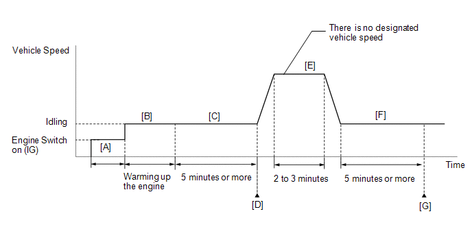
CONFIRMATION DRIVING PATTERN
HINT:
-
After repair has been completed, clear the DTC and then check that the vehicle has returned to normal by performing the following All Readiness check procedure.
Click here
.gif)
-
When clearing the permanent DTCs, refer to the "CLEAR PERMANENT DTC" procedure.
Click here
- Connect the Techstream to the DLC3.
- Turn the engine switch on (IG).
- Turn the Techstream on.
- Clear the DTCs (even if no DTCs are stored, perform the clear DTC procedure).
- Turn the engine switch off and wait for at least 30 seconds.
- Turn the engine switch on (IG) [A].
- Turn the Techstream on.
- Start the engine and warm it up until the engine coolant temperature reaches 75°C (167°F) or higher [B].
- Idle the engine for 5 minutes or more [C].
- Enter the following menus: Powertrain / Engine / Trouble Codes [D].
-
Read the pending DTCs.
HINT:
- If a pending DTC is output, the system is malfunctioning.
- If a pending DTC is not output, perform the following procedure.
- Enter the following menus: Powertrain / Engine / Utility / All Readiness.
- Input the DTC: P001600 or P001800.
-
Check the DTC judgment result.
Techstream Display
Description
NORMAL
- DTC judgment completed
- System normal
ABNORMAL
- DTC judgment completed
- System abnormal
INCOMPLETE
- DTC judgment not completed
- Perform driving pattern after confirming DTC enabling conditions
HINT:
- If the judgment result is NORMAL, the system is normal.
- If the judgment result is ABNORMAL, the system has a malfunction.
- If the judgment result is INCOMPLETE, perform steps [E] through [G].
-
[A] to [D]: Normal judgment procedure.
The normal judgment procedure is used to complete DTC judgment and also used when clearing permanent DTCs.
- When clearing the permanent DTCs, do not disconnect the cable from the battery terminal or attempt to clear the DTCs during this procedure, as doing so will clear the universal trip and normal judgment histories.
-
Drive the vehicle for 2 to 3 minutes [E].
CAUTION:
When performing the confirmation driving pattern, obey all speed limits and traffic laws.
- Idle the engine for 5 minutes or more [F].
- Enter the following menus: Powertrain / Engine / Trouble Codes [G].
-
Read the pending DTCs.
HINT:
- If a pending DTC is output, the system is malfunctioning.
- If a pending DTC is not output, perform the following procedure.
-
Check the DTC judgment result.
HINT:
- If the judgment result is NORMAL, the system is normal.
- If the judgment result is ABNORMAL, the system has a malfunction.
-
[A] to [G]: Normal judgment procedure.
The normal judgment procedure is used to complete DTC judgment and also used when clearing permanent DTCs.
- When clearing the permanent DTCs, do not disconnect the cable from the battery terminal or attempt to clear the DTCs during this procedure, as doing so will clear the universal trip and normal judgment histories.
CAUTION / NOTICE / HINT
HINT:
-
Bank 1 refers to the bank that includes the No. 1 cylinder*.
*: The No. 1 cylinder is the cylinder which is farthest from the transaxle.
- Bank 2 refers to the bank that does not include the No. 1 cylinder.
- The monitor for this DTC detects when the timing chain is shifted by one tooth or more.
- Read freeze frame data using the Techstream. The ECM records vehicle and driving condition information as freeze frame data the moment a DTC is stored. When troubleshooting, freeze frame data can help determine if the vehicle was moving or stationary, if the engine was warmed up or not, if the air fuel ratio was lean or rich, and other data from the time the malfunction occurred.
PROCEDURE
| 1. | PERFORM SIMULATION TEST (CHECK FOR ABNORMAL NOISE) |
(a) Start the engine.
(b) Check for abnormal noise (rattling sounds) from the camshaft timing gear assembly with the engine idling.
| Result | Proceed to |
|---|---|
| Abnormal noise (rattling sound) from the camshaft timing gear assembly is heard. | A |
| Abnormal noise (rattling sound) from the camshaft timing gear assembly is not heard. | B |
HINT:
- As the engine speed increases, the camshaft timing gear assembly lock pins will release and the abnormal noise (rattling sound) will disappear.
-
Perform "Inspection After Repair" after replacing the camshaft timing gear assembly.
Click here
| A | .gif) | REPLACE CAMSHAFT TIMING GEAR BOLT (CAMSHAFT TIMING OIL CONTROL VALVE [FOR INTAKE CAMSHAFT]) AND CAMSHAFT TIMING GEAR ASSEMBLY |
|
.gif)
| 2. | CHECK ANY OTHER DTCS OUTPUT (IN ADDITION TO DTC P001600 OR P001800) |
(a) Connect the Techstream to the DLC3.
(b) Turn the engine switch on (IG).
(c) Turn the Techstream on.
(d) Enter the following menus: Powertrain / Engine / Trouble Codes.
(e) Read the DTCs.
Powertrain > Engine > Trouble Codes| Result | Proceed to |
|---|---|
| DTC P001600 or P001800 is output | A |
| DTC P001600 or P001800 and other DTCs are output | B |
HINT:
If any DTCs other than P001600 or P001800 are output, troubleshoot those DTCs first.
| B | | GO TO DTC CHART |
|
| 3. | PERFORM ACTIVE TEST USING TECHSTREAM (CONTROL THE INTAKE VVT OCV DUTY RATIO) |
HINT:
If the VVT system can be operated through the Active Test, it can be assumed that the VVT system is operating normally.
(a) Connect the Techstream to the DLC3.
(b) Start the engine.
(c) Turn the Techstream on.
(d) Enter the following menus: Powertrain / Engine / Active Test / Control the Intake VVT OCV Duty Ratio Bank 1 or Control the Intake VVT OCV Duty Ratio Bank 2 / Data List / Intake VVT Change Angle Bank 1 or Intake VVT Change Angle Bank 2.
Powertrain > Engine > Active Test| Active Test Display |
|---|
| Control the Intake VVT OCV Duty Ratio Bank 1 |
| Data List Display |
|---|
| Intake VVT Change Angle Bank 1 |
| Active Test Display |
|---|
| Control the Intake VVT OCV Duty Ratio Bank 2 |
| Data List Display |
|---|
| Intake VVT Change Angle Bank 2 |
(e) Perform the Active Test. Check that the displacement angle varies.
OK:
Displacement angle varies.
| NG | | GO TO STEP 5 |
|
| 4. | CHECK ENGINE MECHANICAL SYSTEM |
(a) Check for mechanical malfunctions that affect the valve timing, such as a jumped tooth or stretching of the timing chain.
HINT:
Perform "Inspection After Repair" after repairing or replacing the engine mechanical system.
Click here
| OK | | GO TO STEP 8 |
| NG | | REPAIR OR REPLACE MALFUNCTIONING PARTS, COMPONENT AND AREA |
| 5. | INSPECT CAM TIMING OIL CONTROL SOLENOID ASSEMBLY (FOR INTAKE CAMSHAFT) |
(a) Inspect the cam timing oil control solenoid assembly (for intake camshaft).
Click here
| NG | | REPLACE CAM TIMING OIL CONTROL SOLENOID ASSEMBLY (FOR INTAKE CAMSHAFT) |
|
| 6. | INSPECT CAMSHAFT TIMING GEAR BOLT (CAMSHAFT TIMING OIL CONTROL VALVE ASSEMBLY [FOR INTAKE CAMSHAFT]) |
(a) Inspect the camshaft timing gear bolt (camshaft timing oil control valve assembly [for intake camshaft]).
-
for Bank 1: Click here
-
for Bank 2: Click here
| NG | | REPLACE CAMSHAFT TIMING GEAR BOLT (CAMSHAFT TIMING OIL CONTROL VALVE ASSEMBLY [FOR INTAKE CAMSHAFT]) |
|
| 7. | INSPECT OIL CONTROL VALVE FILTER (FOR INTAKE CAMSHAFT) |
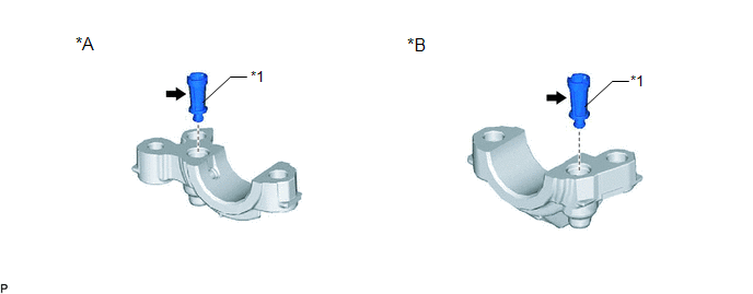
| *A | for Intake Camshaft of Bank 1 | *B | for Intake Camshaft of Bank 2 |
| *1 | Oil Control Valve Filter | - | - |
(a) Remove the oil control valve filter (for intake camshaft of bank 1) or oil control valve filter (for intake camshaft of bank 2).
-
for Bank 1: Click here
-
for Bank 2: Click here
(b) Check that the filter is not clogged.
OK:
Filter is not clogged.
| NG | | REPLACE OIL CONTROL VALVE FILTER (FOR INTAKE CAMSHAFT) |
|
| 8. | CLEAR DTC |
(a) Connect the Techstream to the DLC3.
(b) Turn the engine switch on (IG).
(c) Turn the Techstream on.
(d) Clear the DTC.
Powertrain > Engine > Clear DTCs(e) Turn the engine switch off and wait for at least 30 seconds.
|
| 9. | CHECK WHETHER DTC OUTPUT RECURS (DTC P001600 OR P001800) |
(a) Drive the vehicle in accordance with the driving pattern described in Confirmation Driving Pattern.
(b) Enter the following menus: Powertrain / Engine / Trouble Codes / Pending.
(c) Read the pending DTCs.
Powertrain > Engine > Trouble Codes| Result | Proceed to |
|---|---|
| DTCs are not output | A |
| DTC P001600 or P001800 is output | B |
| A | | CHECK FOR INTERMITTENT PROBLEMS |
|
| 10. | REPLACE CAMSHAFT TIMING GEAR ASSEMBLY |
(a) Replace the camshaft timing gear assembly.
Click here
HINT:
Perform "Inspection After Repair" after replacing the camshaft timing gear assembly.
Click here
|
| 11. | CLEAR DTC |
(a) Connect the Techstream to the DLC3.
(b) Turn the engine switch on (IG).
(c) Turn the Techstream on.
(d) Clear the DTC.
Powertrain > Engine > Clear DTCs(e) Turn the engine switch off and wait for at least 30 seconds.
|
| 12. | CHECK WHETHER DTC OUTPUT RECURS (DTC P001600 OR P001800) |
(a) Drive the vehicle in accordance with the driving pattern described in Confirmation Driving Pattern.
(b) Enter the following menus: Powertrain / Engine / Trouble Codes / Pending.
(c) Read the pending DTCs.
Powertrain > Engine > Trouble Codes| Result | Proceed to |
|---|---|
| DTCs are not output | A |
| DTC P001600 or P001800 is output | B |
| A | | END |
| B | | REPLACE ECM |
READ NEXT:
 Crankshaft Position - Camshaft Position Correlation Bank 1 Sensor B (P001700,P001900)
DESCRIPTION In the VVT (Variable Valve Timing) system, the appropriate exhaust valve open and close timing is controlled by the ECM. The ECM performs exhaust valve control by performing the following:
HO2S Heater Control Bank 1 Sensor 1 Circuit Short to Battery (P003012,P003013,P005012,P005013,P101A9E,P103A9E)
DESCRIPTION Refer to DTC P219519. Click here HINT:
When any of these DTCs are stored, the ECM enters fail-safe mode. The ECM turns off the air fuel ratio sensor heater in fail-safe mode. Fail-saf
HO2S Heater Control Circuit Bank 1 Sensor 2 Circuit Short to Battery (P003612,P003614,P005612,P005614,P014118,P016118,P102A9E,P105A9E)
DESCRIPTION Refer to DTC P013611. Click here HINT:
When any of these DTCs are stored, the ECM enters fail-safe mode. The ECM turns off the heated oxygen sensor heater in fail-safe mode. Fail-safe
SEE MORE:
Precaution
PRECAUTION TROUBLESHOOTING PRECAUTION NOTICE:
Since the brake lines are critical safety related parts, be sure to disassemble and inspect the components if a brake fluid leak is found. If any abnormalities are found, replace the component with a new one.
When removing brake components, cover th
Panel Switches do not Function
CAUTION / NOTICE / HINT NOTICE:
Depending on the parts that are replaced during vehicle inspection or maintenance, performing initialization, registration or calibration may be needed. Refer to Precaution for Navigation System.
Click here
When replacing the radio receiver assembly, always re
