Lexus ES: Parking Light/Daytime Running Light Circuit
DESCRIPTION
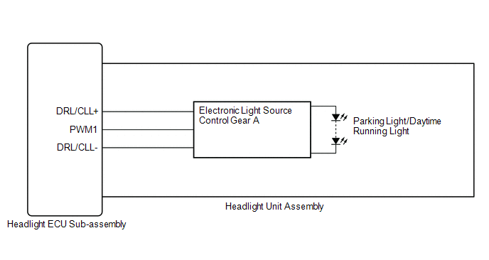
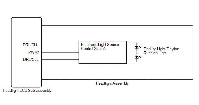
- When the main body ECU (multiplex network body ECU) receives the light control switch position signal, it sends an illumination request signal to the headlight ECU sub-assembly and illuminates the parking lights.
- When the operation conditions of the daytime running lights are met, the main body ECU (multiplex network body ECU) sends an illumination request signal to the headlight ECU sub-assembly and illuminates the daytime running lights.
WIRING DIAGRAM
for TMC Made
for TMMK Made
CAUTION / NOTICE / HINT
NOTICE:
-
If the headlight ECU sub-assembly LH has been replaced, it is necessary to synchronize the vehicle information and initialize the headlight ECU sub-assembly LH.*1
Click here
.gif)
-
If the headlight ECU sub-assembly LH has been replaced, it is necessary to synchronize the vehicle information the headlight ECU sub-assembly LH.*2
Click here
-
If the headlight assembly LH has been replaced, it is necessary to synchronize the vehicle information the headlight ECU sub-assembly LH.*3
Click here
-
When replacing the headlight ECU sub-assembly LH, always replace it with a new one. If a headlight ECU sub-assembly LH which was installed to another vehicle is used, the information stored in it will not match the information from the vehicle and a DTC may be stored.
- *1: for LED Type Turn Signal Light
- *2: for Bulb Type Turn Signal Light
- *3: for Bulb Type Turn Signal Light (for TMMK Made)
PROCEDURE
| 1. | CONFIRM MODEL |
(a) Choose the model to be inspected.
| Result | Proceed to |
|---|---|
| for LED Type Turn Signal Light | A |
| for Bulb Type Turn Signal Light | B |
| B | .gif) | GO TO STEP 5 |
|
.gif)
| 2. | CHECK LIGHTS |
(a) Check the illumination of each parking lights and daytime running lights.
| Result | Proceed to |
|---|---|
| LH side parking light and daytime running light does not illuminate | A |
| RH side parking light and daytime running light does not illuminate | B |
| B | | GO TO STEP 4 |
|
| 3. | PERFORM ACTIVE TEST USING TECHSTREAM |
(a) Connect the Techstream to the DLC3.
(b) Turn the engine switch on (IG).
(c) Turn the Techstream on.
(d) Enter the following menus: Body Electrical / AFS / Active Test.
(e) Perform the Active Test according to the display on the Techstream.
Body Electrical > AFS > Active Test| Tester Display | Measurement Item | Control Range | Diagnostic Note |
|---|---|---|---|
| Clearance Light | Parking lights | OFF or ON | - |
| Daytime Running Light | Daytime running lights | OFF or ON | - |
| Tester Display |
|---|
| Clearance Light |
| Tester Display |
|---|
| Daytime Running Light |
OK:
Parking lights and daytime running lights illuminate.
| OK | | PROCEED TO NEXT SUSPECTED AREA SHOWN IN PROBLEM SYMPTOMS TABLE |
| NG | | GO TO STEP 7 |
| 4. | PERFORM ACTIVE TEST USING TECHSTREAM |
(a) Connect the Techstream to the DLC3.
(b) Turn the engine switch on (IG).
(c) Turn the Techstream on.
(d) Enter the following menus: Body Electrical / AFS (Sub) / Active Test.
(e) Perform the Active Test according to the display on the Techstream.
Body Electrical > AFS (Sub) > Active Test| Tester Display | Measurement Item | Control Range | Diagnostic Note |
|---|---|---|---|
| Clearance Light | Parking lights | OFF or ON | - |
| Daytime Running Light | Daytime running lights | OFF or ON | - |
| Tester Display |
|---|
| Clearance Light |
| Tester Display |
|---|
| Daytime Running Light |
OK:
Parking lights and daytime running lights illuminate.
| OK | | PROCEED TO NEXT SUSPECTED AREA SHOWN IN PROBLEM SYMPTOMS TABLE |
| NG | | GO TO STEP 12 |
| 5. | CHECK LIGHTS |
(a) Check the illumination of each parking lights and daytime running lights.
| Result | Proceed to |
|---|---|
| LH side parking light and daytime running light does not illuminate | A |
| RH side parking light and daytime running light does not illuminate | B |
| B | | GO TO STEP 11 |
|
| 6. | PERFORM ACTIVE TEST USING TECHSTREAM |
(a) Connect the Techstream to the DLC3.
(b) Turn the engine switch on (IG).
(c) Turn the Techstream on.
(d) Enter the following menus: Body Electrical / HL AutoLeveling / Active Test.
(e) Perform the Active Test according to the display on the Techstream.
Body Electrical > HL AutoLeveling > Active Test| Tester Display | Measurement Item | Control Range | Diagnostic Note |
|---|---|---|---|
| Clearance Light | Parking lights | OFF or ON | - |
| Daytime Running Light | Daytime running lights | OFF or ON | - |
| Tester Display |
|---|
| Clearance Light |
| Tester Display |
|---|
| Daytime Running Light |
OK:
Parking lights and daytime running lights illuminate.
| Result | Proceed to |
|---|---|
| OK | A |
| NG (for TMC Made) | B |
| NG (for TMMK Made) | C |
| A | | PROCEED TO NEXT SUSPECTED AREA SHOWN IN PROBLEM SYMPTOMS TABLE |
| C | | GO TO STEP 9 |
|
| 7. | CHECK HEADLIGHT UNIT ASSEMBLY LH |
(a) Interchange the headlight unit assembly LH with RH and connect the connectors.
for LED Type Turn Signal Light: Click here
for Bulb Type Turn Signal Light: Click here
|
| 8. | CHECK OPERATION (PARKING LIGHTS AND DAYTIME RUNNING LIGHTS) |
(a) Check the operation of the parking lights and daytime running lights.
OK:
The parking lights and daytime running lights operate normally.
| OK | | REPLACE HEADLIGHT ECU SUB-ASSEMBLY LH |
| NG | | REPLACE HEADLIGHT UNIT ASSEMBLY LH |
| 9. | CHECK HEADLIGHT ASSEMBLY LH |
(a) Remove each headlight ECU sub-assembly, interchange the headlight assembly LH with RH and connect the connectors.
Click here
|
| 10. | CHECK OPERATION (PARKING LIGHTS AND DAYTIME RUNNING LIGHTS) |
(a) Check the operation of the parking lights and daytime running lights.
OK:
The parking lights and daytime running lights operate normally.
| OK | | REPLACE HEADLIGHT ECU SUB-ASSEMBLY LH |
| NG | | REPLACE HEADLIGHT ASSEMBLY LH |
| 11. | PERFORM ACTIVE TEST USING TECHSTREAM |
(a) Connect the Techstream to the DLC3.
(b) Turn the engine switch on (IG).
(c) Turn the Techstream on.
(d) Enter the following menus: Body Electrical / HL AutoLeveling (Sub) / Active Test.
(e) Perform the Active Test according to the display on the Techstream.
Body Electrical > HL AutoLeveling (Sub) > Active Test| Tester Display | Measurement Item | Control Range | Diagnostic Note |
|---|---|---|---|
| Clearance Light | Parking lights | OFF or ON | - |
| Daytime Running Light | Daytime running lights | OFF or ON | - |
| Tester Display |
|---|
| Clearance Light |
| Tester Display |
|---|
| Daytime Running Light |
OK:
Parking lights and daytime running lights illuminate.
| Result | Proceed to |
|---|---|
| OK | A |
| NG (for TMC Made) | B |
| NG (for TMMK Made) | C |
| A | | PROCEED TO NEXT SUSPECTED AREA SHOWN IN PROBLEM SYMPTOMS TABLE |
| C | | GO TO STEP 14 |
|
| 12. | CHECK HEADLIGHT UNIT ASSEMBLY RH |
(a) Interchange the headlight unit assembly RH with LH and connect the connectors.
for LED Type Turn Signal Light: Click here
for Bulb Type Turn Signal Light: Click here
|
| 13. | CHECK OPERATION (PARKING LIGHTS AND DAYTIME RUNNING LIGHTS) |
(a) Check the operation of the parking lights and daytime running lights.
OK:
The parking lights and daytime running lights operate normally.
| OK | | REPLACE HEADLIGHT ECU SUB-ASSEMBLY RH |
| NG | | REPLACE HEADLIGHT UNIT ASSEMBLY RH |
| 14. | CHECK HEADLIGHT ASSEMBLY RH |
(a) Remove each headlight ECU sub-assembly, interchange the headlight assembly RH with LH and connect the connectors.
Click here
|
| 15. | CHECK OPERATION (PARKING LIGHTS AND DAYTIME RUNNING LIGHTS) |
(a) Check the operation of the parking lights and daytime running lights.
OK:
The parking lights and daytime running lights operate normally.
| OK | | REPLACE HEADLIGHT ECU SUB-ASSEMBLY RH |
| NG | | REPLACE HEADLIGHT ASSEMBLY RH |
READ NEXT:
 Hazard Warning Switch Circuit
DESCRIPTION The combination meter assembly receives the hazard warning signal switch assembly on signal and controls the operation of the hazard warning lights. WIRING DIAGRAM CAUTION / NOTICE / HINT
Outside Handle Foot Light Circuit
DESCRIPTION The main body ECU (multiplex network body ECU) controls the outside handle foot lights. WIRING DIAGRAM CAUTION / NOTICE / HINT NOTICE: Before replacing the main body ECU (multiplex networ
Front Side Marker Light Circuit
DESCRIPTION When the light control switch is in the tail or head position, the main body ECU (multiplex network body ECU) sends an illumination request signal to the headlight ECU sub-assembly to illu
SEE MORE:
Drive Motor "A" Inverter Voltage Sensor(VH) Circuit Voltage Above Threshold (P0C7917)
DTC SUMMARY MALFUNCTION DESCRIPTION If an overvoltage malfunction occurs in the motor inverter or generator inverter, the motor generator control ECU (MG ECU) detects the malfunction and stores this DTC. The cause of this malfunction may be one of the following: Area Main Malfunction Descriptio
Rear Disc Brake Pad
ComponentsCOMPONENTS ILLUSTRATION *1 NO. 2 PARKING BRAKE WIRE ASSEMBLY *2 REAR DISC BRAKE ANTI-SQUEAL SHIM KIT *3 REAR DISC BRAKE PAD *4 REAR DISC BRAKE CYLINDER ASSEMBLY *5 REAR NO. 1 DISC BRAKE ANTI-SQUEAL SHIM *6 REAR NO. 2 DISC BRAKE ANTI-SQUEAL SHIM *7 REAR
