Lexus ES: Panoramic Moon Roof System does not Operate
DESCRIPTION
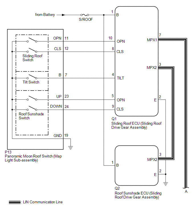
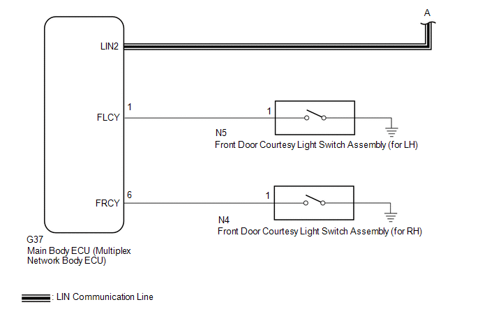
The sliding roof ECU (sliding roof drive gear assembly) and roof sunshade ECU (sliding roof drive gear assembly) receive each other's position information from the main body ECU (multiplex network body ECU) via LIN communication.
The sliding roof ECU (sliding roof drive gear assembly) and roof sunshade ECU (sliding roof drive gear assembly) receive signals from each switch, and operate their built-in motors.
For the linked functions of the sliding roof and roof sunshade refer to Operation Check.
Click here .gif)
WIRING DIAGRAM
CAUTION / NOTICE / HINT
NOTICE:
- Inspect the fuses for circuits related to this system before performing the following procedure.
-
The sliding roof auto operation function can be customized. Make sure that the function is set to ON.
Click here
-
If the sliding roof ECU (sliding roof drive gear assembly) or roof sunshade ECU (sliding roof drive gear assembly) is removed and reinstalled or replaced, the sliding roof ECU (sliding roof drive gear assembly) or roof sunshade ECU (sliding roof drive gear assembly) must be initialized.
Click here
-
The panoramic moon roof system uses the CAN and LIN communication systems. First, confirm that there are no malfunctions in the CAN and LIN communication systems. Refer to How to Proceed with Troubleshooting.
Click here
-
If a sliding roof ECU (sliding roof drive gear assembly) or roof sunshade ECU (sliding roof drive gear assembly) DTC is output,perform troubleshooting for the DTC first.
Click here
PROCEDURE
| 1. | CHECK FOR DTC (MAIN BODY) |
(a) Clear the DTCs.
Body Electrical > Main Body > Clear DTCs(b) Check for DTCs.
Body Electrical > Main Body > Trouble CodesOK:
DTCs B1273 are not output.
| NG | .gif) | GO TO LIN COMMUNICATION SYSTEM (Proceed to How to Proceed with Troubleshooting) |
|
.gif)
| 2. | CHECK FOR DTC (SLIDING ROOF AND SLIDING SUNSHADE) |
(a) Clear the DTCs.
Body Electrical > Sliding Roof > Clear DTCs(b) Check for DTCs.
Body Electrical > Sliding Roof > Trouble CodesOK:
DTCs B2341 and B2344 are not output.
| NG | | GO TO DIAGNOSTIC TROUBLE CODE CHART |
|
| 3. | CHECK POWER WINDOW CONTROL SYSTEM |
(a) Check the power window control system operates normally.
Click here
OK:
The power window control system operates normally.
| NG | | GO TO POWER WINDOW CONTROL SYSTEM |
|
| 4. | PERFORM ACTIVE TEST USING TECHSTREAM (SLIDING ROOF) |
(a) Connect the Techstream to the DLC3.
(b) Turn the engine switch on (IG).
(c) Turn the Techstream on.
(d) Enter the following menus: Body Electrical / Sliding Roof / Active Test.
(e) Perform the Active Test according to the display on the Techstream.
Body Electrical > Sliding Roof > Active Test| Tester Display | Measurement Item | Control Range | Diagnostic Note |
|---|---|---|---|
| Slide Roof | Operate sliding roof motor | OFF / Opn/Dwn / Clos/Up | - |
| Tester Display |
|---|
| Slide Roof |
OK:
Slide roof is operated using Techstream.
| NG | | GO TO STEP 9 |
|
| 5. | READ VALUE USING TECHSTREAM (SLIDING ROOF) |
(a) Connect the Techstream to the DLC3.
(b) Turn the engine switch on (IG).
(c) Turn the Techstream on.
(d) Enter the following menus: Body Electrical / Sliding Roof / Data List.
(e) Read the Data List according to the display on the Techstream.
Body Electrical > Sliding Roof > Data List| Tester Display | Measurement Item | Range | Normal Condition | Diagnostic Note |
|---|---|---|---|---|
| Open Switch | Sliding roof open switch signal | OFF or ON | OFF: Sliding roof switch not slid backward ON: Sliding roof switch slid backward | - |
| Close Switch | Sliding roof close switch signal | OFF or ON | OFF: Sliding roof switch not slid forward ON: Sliding roof switch slid forward | - |
| Up Switch | Roof sunshade close switch signal | OFF or ON | OFF: Roof sunshade switch not slid forward ON: Roof sunshade switch slid forward | - |
| Down Switch | Roof sunshade open switch signal | OFF or ON | OFF: Roof sunshade switch not slid backward ON: Roof sunshade switch slid backward | - |
| Tester Display |
|---|
| Open Switch |
| Close Switch |
| Up Switch |
| Down Switch |
OK:
The Techstream display changes according to switch operation as shown in the table.
| NG | | GO TO STEP 7 |
|
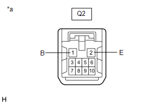
| 6. | CHECK HARNESS AND CONNECTOR (ROOF SUNSHADE ECU (SLIDING ROOF DRIVE GEAR ASSEMBLY) - BATTERY AND BODY GROUND) |
| (a) Disconnect the Q2 roof sunshade ECU (sliding roof drive gear assembly) connector. |
|
(b) Measure the voltage according to the value(s) in the table below.
Standard Voltage:
| Tester Connection | Condition | Specified Condition |
|---|---|---|
| Q2-1 (B) - Body ground | Always | 11 to 14 V |
(c) Measure the resistance according to the value(s) in the table below.
Standard Resistance:
| Tester Connection | Condition | Specified Condition |
|---|---|---|
| Q2-2 (E) - Body ground | Always | Below 1 Ω |
| OK | | REPLACE ROOF SUNSHADE ECU (SLIDING ROOF DRIVE GEAR ASSEMBLY) |
| NG | | REPAIR OR REPLACE HARNESS OR CONNECTOR |
| 7. | INSPECT PANORAMIC MOON ROOF SWITCH (MAP LIGHT SUB-ASSEMBLY) |
(a) Remove the panoramic moon roof switch (map light sub-assembly).
Click here
(b) Inspect the panoramic moon roof switch (map light sub-assembly).
Click here
| NG | | REPLACE PANORAMIC MOON ROOF SWITCH (MAP LIGHT SUB-ASSEMBLY) |
|
| 8. | CHECK HARNESS AND CONNECTOR (SLIDING ROOF ECU (SLIDING ROOF DRIVE GEAR ASSEMBLY) - PANORAMIC MOON ROOF SWITCH (MAP LIGHT SUB-ASSEMBLY) AND BODY GROUND) |
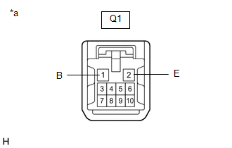
(a) Disconnect the Q1 sliding roof ECU (sliding roof drive gear assembly) connector.
(b) Disconnect the P13 panoramic moon roof switch (map light sub-assembly) connector.
(c) Measure the resistance according to the value(s) in the table below.
Standard Resistance:
| Tester Connection | Condition | Specified Condition |
|---|---|---|
| Q1-10 (OPN) - P13-11 (OPN) | Always | Below 1 Ω |
| Q1-10 (OPN) or P13-11 (OPN) - Body ground | Always | 10 kΩ or higher |
| Q1-8 (CLS) - P13-12 (CLS) | Always | Below 1 Ω |
| Q1-8 (CLS) or P13-12 (CLS) - Body ground | Always | 10 kΩ or higher |
| Q1-4 (TILT) - P13-7 (B) | Always | Below 1 Ω |
| Q1-4 (TILT) or P13-7 (B) - Body ground | Always | 10 kΩ or higher |
| Q1-5 (OPN) - P13-23 (UP) | Always | Below 1 Ω |
| Q1-5 (OPN) or P13-23 (UP) - Body ground | Always | 10 kΩ or higher |
| Q1-9 (CLS) - P13-24 (DOWN) | Always | Below 1 Ω |
| Q1-9 (CLS) or P13-24 (DOWN) - Body ground | Always | 10 kΩ or higher |
| Q1-2 (E) - Body ground | Always | Below 1 Ω |
| P13-19 (GND) - Body ground | Always | Below 1 Ω |
| OK | | REPLACE SLIDING ROOF ECU (SLIDING ROOF DRIVE GEAR ASSEMBLY) |
| NG | | REPAIR OR REPLACE HARNESS OR CONNECTOR |
| 9. | CHECK HARNESS AND CONNECTOR (SLIDING ROOF ECU (SLIDING ROOF DRIVE GEAR ASSEMBLY) - BATTERY AND BODY GROUND) |
| (a) Disconnect the Q1 sliding roof ECU (sliding roof drive gear assembly) connector. |
|
(b) Measure the voltage according to the value(s) in the table below.
Standard Voltage:
| Tester Connection | Condition | Specified Condition |
|---|---|---|
| Q1-1 (B) - Body ground | Always | 11 to 14 V |
(c) Measure the resistance according to the value(s) in the table below.
Standard Resistance:
| Tester Connection | Condition | Specified Condition |
|---|---|---|
| Q1-2 (E) - Body ground | Always | Below 1 Ω |
| OK | | REPLACE SLIDING ROOF ECU (SLIDING ROOF DRIVE GEAR ASSEMBLY) |
| NG | | REPAIR OR REPLACE HARNESS OR CONNECTOR |
READ NEXT:
 Components
COMPONENTS ILLUSTRATION *A for Front Side *B for Rear Side *1 FRONT SLIDING ROOF GARNISH LH *2 FRONT SLIDING ROOF GARNISH RH *3 SLIDING ROOF GLASS SUB-ASSEMBLY *4 SLIDING
Removal
REMOVAL CAUTION / NOTICE / HINT The necessary procedures (adjustment, calibration, initialization or registration) that must be performed after parts are removed and installed, or replaced during slid
SEE MORE:
Data List / Active Test
DATA LIST / ACTIVE TEST DATA LIST HINT: Using the Techstream to read the Data List allows the values or states of switches, sensors, actuators and other items to be read without removing any parts. This non-intrusive inspection can be very useful because intermittent conditions or signals may be dis
Front seats
The seats can be adjusted (longitudinally,
vertically, etc.). Adjust the
seat to ensure the correct driving
posture.
Adjustment procedure
Seat position adjustment
Seatback angle adjustment
Seat cushion (front) angle adjustment
Vertical height adjustment
Lumbar support adjustment
