Lexus ES: Operation Check
OPERATION CHECK
PKSB OFF INDICATOR LIGHT OPERATION CHECK
(a) Turn the power switch on (IG).
(b) Turn the parking support brake system off and confirm that the PKSB OFF indicator in the combination meter illuminates.
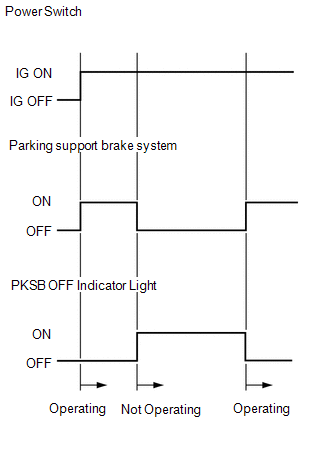
HINT:
If the parking support brake system is not set to off in the customize settings, the parking support brake system will operate when the power switch is turned on (IG).
DETECTION AREA
(a) Parking support brake system detection distance
-
The ultrasonic sensors (front/rear center sensor) can detect objects up to a distance of approximately 4.0 m (13.124 ft.). However, the detection distance varies depending on the shape of the object.
.png)
HINT:
The detection range shown in the illustration is for when detecting an object that is 2.0 m (6.562 ft.) wide, 1.0 m (3.281 ft.) tall and is perpendicular to the ground.
- If the front/rear sensors and left/right sensors do not simultaneously detect an object, the parking support brake function does not operate.
NOTICE:
Even if the parking support brake system detects an object, the system may not operate depending on the vehicle conditions.
READ NEXT:
 Parts Location
PARTS LOCATION ILLUSTRATION *1 FRONT CORNER ULTRASONIC SENSOR RH *2 FRONT CENTER ULTRASONIC SENSOR RH *3 FRONT CENTER ULTRASONIC SENSOR LH *4 FRONT CORNER ULTRASONIC SENSOR LH
Precaution
PRECAUTION PRECAUTION FOR DISCONNECTING CABLE FROM NEGATIVE AUXILIARY BATTERY TERMINAL NOTICE: When disconnecting the cable from the negative (-) auxiliary battery terminal, initialize the following s
Problem Symptoms Table
PROBLEM SYMPTOMS TABLE HINT:
Use the table below to help determine the cause of problem symptoms. If multiple suspected areas are listed, the potential causes of the symptoms are listed in order of
SEE MORE:
Problem Symptoms Table
PROBLEM SYMPTOMS TABLE NOTICE:
Before replacing the ECM, refer to Registration.
Click here
When replacing the millimeter wave radar sensor assembly, always replace it with a new one. If a millimeter wave radar sensor assembly which was installed to another vehicle is used, the information st
Problem Symptoms Table
PROBLEM SYMPTOMS TABLE HINT:
Use the table below to help determine the cause of problem symptoms. If multiple suspected areas are listed, the potential causes of the symptoms are listed in order of probability in the "Suspected Area" column of the table. Check each symptom by checking the suspect
