Lexus ES: Open or Short in Steering Angle Sensor +B (C1625)
DESCRIPTION
This DTC is stored if the clearance warning ECU assembly receives a signal via CAN communication from the steering sensor that indicates a power supply problem.
| DTC No. | Detection Item | DTC Detection Condition | Trouble Area |
|---|---|---|---|
| C1625 | Open or Short in Steering Angle Sensor +B | Open or short in steering sensor power source |
|
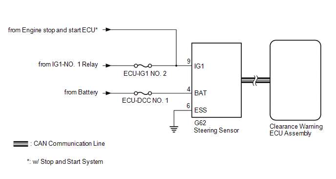
WIRING DIAGRAM
CAUTION / NOTICE / HINT
NOTICE:
-
After turning the engine switch off, waiting time may be required before disconnecting the cable from the negative (-) battery terminal. Therefore make sure to read the disconnecting the cable from the negative (-) battery terminal notices before proceeding with work.
Click here
.gif)
-
After replacing an ultrasonic sensor or the clearance warning ECU assembly, perform the necessary procedures (adjustment, calibration, initialization or registration).
Click here
- Inspect the fuses for circuits related to this system before performing the following procedure.
PROCEDURE
| 1. | CHECK HARNESS AND CONNECTOR (STEERING SENSOR POWER SOURCE) |
(a) Disconnect the G62 steering sensor connector.
(b) Measure the voltage according to the value(s) in the table below.
Standard Voltage:
| Tester Connection | Condition | Specified Condition |
|---|---|---|
| G62-9 (IG1) - G62-6 (ESS) | Engine switch on (IG) | 11 to 14 V |
| NG |  | REPAIR OR REPLACE HARNESS OR CONNECTOR |
|

| 2. | CHECK HARNESS AND CONNECTOR (STEERING SENSOR POWER SOURCE) |
(a) Measure the resistance according to the value(s) in the table below.
Standard Resistance:
| Tester Connection | Condition | Specified Condition |
|---|---|---|
| G62-6 (ESS) - Body ground | Always | Below 1 Ω |
(b) Measure the voltage according to the value(s) in the table below.
Standard Voltage:
| Tester Connection | Condition | Specified Condition |
|---|---|---|
| G62-4 (BAT) - G62-6 (ESS) | Always | 11 to 14 V*1 10.5 to 16 V*2 |
- *1: w/o Stop and Start System
- *2: w/ Stop and Start System
| OK | | REPLACE STEERING SENSOR |
| NG | | REPAIR OR REPLACE HARNESS OR CONNECTOR |
READ NEXT:
 Steering Angle Sensor Failure (C1626)
DESCRIPTION This DTC is stored if the clearance warning ECU assembly receives a signal via CAN communication from the steering sensor that indicates an internal malfunction. DTC No. Detection Ite
G Sensor Failure (C1647)
DESCRIPTION The clearance warning sonar ECU assembly communicates with the airbag sensor assembly (yaw rate and acceleration sensor) via CAN communication, and if it is determined that the airbag sens
Outside Air Temperature Sensor (C1652)
DESCRIPTION When a malfunction signal sent from the air conditioning system via CAN communication is detected by the clearance warning ECU assembly, DTC C1652 is stored. DTC No. Detection Item
SEE MORE:
Data List / Active Test
DATA LIST / ACTIVE TEST DATA LIST HINT: Using the Techstream to read the Data List allows the values or states of switches, sensors, actuators and other items to be read without removing any parts. This non-intrusive inspection can be very useful because intermittent conditions or signals may be dis
Accumulator Low Pressure (C1256)
DESCRIPTION The accumulator pressure sensor is built into the brake actuator (brake booster with master cylinder assembly) and detects the accumulator pressure. The skid control ECU (brake booster with master cylinder assembly) turns on the brake warning light / red (malfunction) and brake warning l
