Lexus ES: Open or Short Circuit in Back Camera Signal (C1622)
DESCRIPTION
DTC C1622 is stored if the parking assist ECU judges as a result of its self check that the signals or signal lines between the parking assist ECU and the rear television camera assembly are not normal.
| DTC No. | Detection Item | DTC Detection Condition | Trouble Area |
|---|---|---|---|
| C1622 | Open or Short Circuit in Back Camera Signal | Open or short in the rear television camera signal circuit |
|
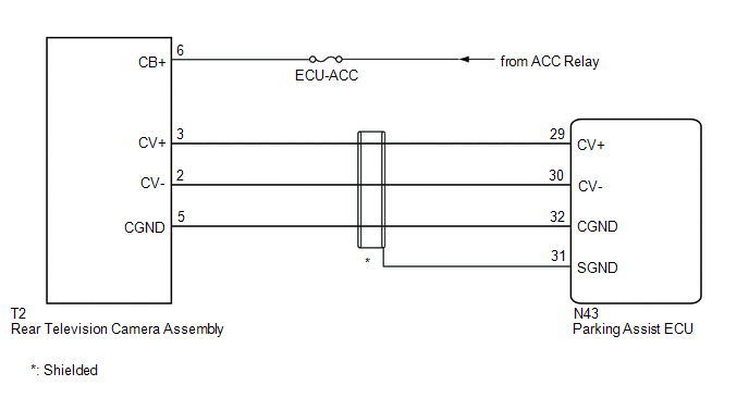
WIRING DIAGRAM
CAUTION / NOTICE / HINT
NOTICE:
- Inspect the fuses for circuits related to this system before performing the following procedure.
-
When "!" is displayed on the multi-display assembly after the cable is disconnected from the negative (-) battery terminal, correct the steering angle neutral point.
Click here
.gif)
-
Depending on the parts that are replaced or operations that are performed during vehicle inspection or maintenance, calibration of other systems as well as the panoramic view monitor system may be needed.
Click here
PROCEDURE
| 1. | CHECK HARNESS AND CONNECTOR (PARKING ASSIST ECU - REAR TELEVISION CAMERA ASSEMBLY) |
(a) Disconnect the N43 parking assist ECU connector.
(b) Disconnect the T2 rear television camera assembly connector.
(c) Measure the resistance according to the value(s) in the table below.
Standard Resistance:
| Tester Connection | Condition | Specified Condition |
|---|---|---|
| N43-29 (CV+) - T2-3 (CV+) | Always | Below 1 Ω |
| N43-30 (CV-) - T2-2 (CV-) | Always | Below 1 Ω |
| N43-32 (CGND) - T2-5 (CGND) | Always | Below 1 Ω |
| N43-29 (CV+) or T2-3 (CV+) - Body ground | Always | 10 kΩ or higher |
| N43-30 (CV-) or T2-2 (CV-) - Body ground | Always | 10 kΩ or higher |
| N43-32 (CGND) or T2-5 (CGND) - Body ground | Always | 10 kΩ or higher |
| NG |  | REPAIR OR REPLACE HARNESS OR CONNECTOR |
|

| 2. | CHECK HARNESS AND CONNECTOR (ACC POWER SUPPLY - GROUND) |
(a) Measure the voltage according to the value(s) in the table below.
Standard Voltage:
| Tester Connection | Condition | Specified Condition |
|---|---|---|
| T2-6 (CB+) - Body ground | Engine switch on (IG) | 11 to 14 V |
| NG | | REPAIR OR REPLACE HARNESS OR CONNECTOR |
|
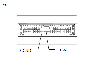
| 3. | CHECK PARKING ASSIST ECU (CV-, CGND) |
(a) Disconnect the N43 parking assist ECU connector.
| (b) Measure the resistance according to the value(s) in the table below. Standard Resistance:
|
|
| NG | | REPLACE PARKING ASSIST ECU |
|
| 4. | CHECK REAR TELEVISION CAMERA ASSEMBLY (CV+, CGND) |
(a) Remove the parking assist ECU with the connector still connected.
(b) Using an oscilloscope, check the waveform of the rear television camera assembly.
HINT:
A waterproof connector is used for the rear television camera assembly. Therefore, inspect the waveform at the parking assist ECU with the connector connected.
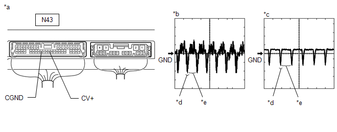
| *a | Component with harness connected (Parking Assist ECU) | *b | Waveform 1 (camera lens not covered, displaying an image) |
| *c | Waveform 2 (camera lens covered, blacking out the screen) | *d | Synchronization Signal |
| *e | Video Waveform | - | - |
HINT:
- The video waveform changes according to the image sent by the rear television camera assembly.
- The video waveform is constantly output when the engine switch is on (ACC).
| Item | Content |
|---|---|
| Terminal No. (Symbol) | N43-29 (CV+) - N43-32 (CGND) |
| Tool Setting | 200 mV/DIV., 50 μsec./DIV. |
| Condition | Engine switch on (IG), panoramic view monitor system operating |
OK:
Waveform is similar to that shown in the illustration.
| OK | | REPLACE PARKING ASSIST ECU |
| NG | | REPLACE REAR TELEVISION CAMERA ASSEMBLY |
READ NEXT:
 Open or Short in Steering Angle Sensor +B (C1625)
DESCRIPTION
This DTC is stored if the parking assist ECU receives a signal via CAN communication from the steering sensor that indicates a power supply system problem.
This DTC is stored if the r
Steering Angle Sensor Failure (C1626)
DESCRIPTION
This DTC is stored if the parking assist ECU receives a signal via CAN communication from the steering sensor that indicates an internal malfunction.
This DTC is stored if the rear te
Front Camera Feedback Malfunction (C1681)
DESCRIPTION DTC C1681 is stored if the parking assist ECU judges as a result of its self check that a synchronization problem is occurring in the image signal sent from the front television camera ass
SEE MORE:
Components
COMPONENTS ILLUSTRATION *A for HV Model *B for Gasoline Model *1 REAR DOOR SCUFF PLATE LH *2 REAR DOOR SCUFF PLATE RH *3 REAR SEAT SIDE GARNISH LH *4 REAR SEAT SIDE GARNISH RH *5 ROOF SIDE INNER GARNISH ASSEMBLY LH *6 ROOF SIDE INNER GARNISH ASSEMBLY RH *7
Registration
REGISTRATION PROCEDURE 1. REGISTER TRANSMITTER CODE HINT:
The vehicle garage door opener records transmitter codes for systems such as garage doors, gates, entry gates, door locks, home lighting systems, security systems or other transmitter code based systems.
The garage door opener is built i
