Lexus ES: Front Camera Feedback Malfunction (C1681)
DESCRIPTION
DTC C1681 is stored if the parking assist ECU judges as a result of its self check that a synchronization problem is occurring in the image signal sent from the front television camera assembly to the parking assist ECU.
| DTC No. | Detection Item | DTC Detection Condition | Trouble Area |
|---|---|---|---|
| C1681 | Front Camera Feedback Malfunction | Front television camera power supply failure |
|
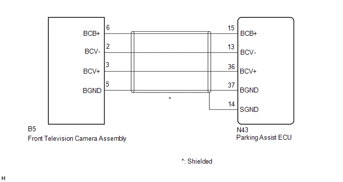
WIRING DIAGRAM
CAUTION / NOTICE / HINT
NOTICE:
-
When "!" is displayed on the multi-display assembly after the cable is disconnected from the negative (-) battery terminal, correct the steering angle neutral point.
Click here
.gif)
-
Depending on the parts that are replaced or operations that are performed during vehicle inspection or maintenance, calibration of other systems as well as the panoramic view monitor system may be needed.
Click here
PROCEDURE
| 1. | CHECK HARNESS AND CONNECTOR (PARKING ASSIST ECU - FRONT TELEVISION CAMERA ASSEMBLY) |
(a) Disconnect the N43 parking assist ECU connector.
(b) Disconnect the B5 front television camera assembly connector.
(c) Measure the resistance according to the value(s) in the table below.
Standard Resistance:
| Tester Connection | Condition | Specified Condition |
|---|---|---|
| N43-15 (BCB+) - B5-6 (BCB+) | Always | Below 1 Ω |
| N43-36 (BCV+) - B5-3 (BCV+) | Always | Below 1 Ω |
| N43-13 (BCV-) - B5-2 (BCV-) | Always | Below 1 Ω |
| N43-37 (BGND) - B5-5 (BGND) | Always | Below 1 Ω |
| N43-14 (SGND) - Body ground | Always | 10 kΩ or higher |
| N43-15 (BCB+) or B5-6 (BCB+) - Body ground | Always | 10 kΩ or higher |
| N43-36 (BCV+) or B5-3 (BCV+) - Body ground | Always | 10 kΩ or higher |
| N43-13 (BCV-) or B5-2 (BCV-) - Body ground | Always | 10 kΩ or higher |
| N43-37 (BGND) or B5-5 (BGND) - Body ground | Always | 10 kΩ or higher |
| NG |  | REPAIR OR REPLACE HARNESS OR CONNECTOR |
|

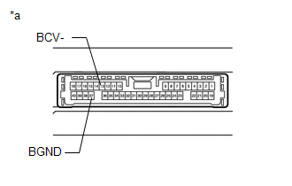
| 2. | CHECK PARKING ASSIST ECU (BCV-, BGND) |
(a) Disconnect the N43 parking assist ECU connector.
| (b) Measure the resistance according to the value(s) in the table below. Standard Resistance:
|
|
| NG | | REPLACE PARKING ASSIST ECU |
|
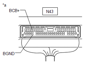
| 3. | CHECK PARKING ASSIST ECU (BCB+, BGND) |
| (a) Remove the parking assist ECU with the connector still connected. |
|
(b) Measure the resistance according to the value(s) in the table below.
Standard Resistance:
| Tester Connection | Condition | Specified Condition |
|---|---|---|
| N43-37 (BGND) - Body ground | Always | Below 1 Ω |
(c) Measure the voltage according to the value(s) in the table below.
Standard Voltage:
| Tester Connection | Condition | Specified Condition |
|---|---|---|
| N43-15 (BCB+) - N43-37 (BGND) | Engine switch on (IG) | 5.5 to 7.05 V |
| NG | | REPLACE PARKING ASSIST ECU |
|
| 4. | CHECK FRONT TELEVISION CAMERA ASSEMBLY (BCV+, BGND) |
(a) Remove the parking assist ECU with the connector still connected.
(b) Using an oscilloscope, check the waveform of the front television camera assembly.
HINT:
A waterproof connector is used for the front television camera assembly. Therefore, inspect the waveform at the parking assist ECU with the connector connected.
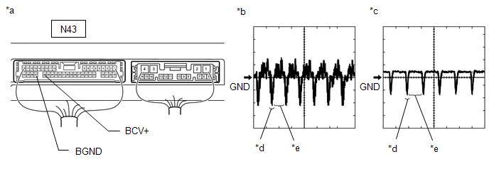
| *a | Component with harness connected (Parking Assist ECU) | *b | Waveform 1 (camera lens not covered, displaying an image) |
| *c | Waveform 2 (camera lens covered, blacking out the screen) | *d | Synchronization Signal |
| *e | Video Waveform | - | - |
HINT:
- The video waveform changes according to the image sent by the front television camera assembly.
- The video waveform is constantly output when the engine switch is on (ACC).
| Item | Content |
|---|---|
| Terminal No. (Symbol) | N43-36 (BCV+) - N43-37 (BGND) |
| Tool Setting | 200 mV/DIV., 50 μsec./DIV. |
| Condition | Engine switch on (IG), panoramic view monitor system operating |
OK:
Waveform is similar to that shown in the illustration.
| OK | | REPLACE PARKING ASSIST ECU |
| NG | | REPLACE FRONT TELEVISION CAMERA ASSEMBLY |
READ NEXT:
 Front Camera Current Malfunction (C1682)
DESCRIPTION DTC C1682 is stored if the parking assist ECU judges as a result of its self check that there is a problem with the current supplied from the front television camera assembly connected to
Side Camera Feedback Malfunction (C1683)
DESCRIPTION This DTC is stored if the parking assist ECU judges as a result of its self check that a synchronization problem is occurring in the image signal sent from the passenger side television ca
Side Camera Current Malfunction (C1684)
DESCRIPTION This DTC is stored if the parking assist ECU judges as a result of its self check that a synchronization problem is occurring in the image signal sent from the passenger side television ca
SEE MORE:
Drive Motor "A" Control Module Internal Electronic Failure (P0A1B49)
DESCRIPTION The MG ECU, which is built into the inverter with converter assembly, monitors its internal operation and will store DTCs if the system is malfunctioning. DTC No. Detection Item DTC Detection Condition Trouble Area MIL Warning Indicate P0A1B49 Drive Motor "A" Control M
Motor Resolver Circuit
DESCRIPTION The cause of this malfunction may be the motor resolver. Check the motor resolver internal resistance and the connection condition from the inverter to the resolver. Related Parts Check Area Inspection Wire harness and connector between the inverter and motor resolver Check fo
