Lexus ES: Open in Stop Switch Circuit (C1425,P0573)
DESCRIPTION
The skid control ECU (brake booster with master cylinder assembly) detects the brake operating conditions through a signal transmitted by the stop light switch assembly.
The skid control ECU incorporates a circuit to detect an open circuit. This DTC is output when an open circuit is detected in the stop light signal input line.
| DTC No. | Detection Item | INF Code | DTC Detection Condition | Trouble Area | MIL | Note |
|---|---|---|---|---|---|---|
| C1425 | Open in Stop Switch Circuit | 231 | An open stop light switch circuit continues for 10 seconds or more. |
| Comes on |
|
| P0573 | Brake Switch "A" Circuit High | - | The stop light switch assembly is stuck 10 times or more. |
| Comes on | - |
MONITOR DESCRIPTION
When the voltage at terminal STP is outside the range of that when the stop light switch assembly is on or the range of that when the stop light switch assembly is off for a certain amount of time, the skid control ECU (brake booster with master cylinder assembly) judges that there is an open in the stop light switch assembly circuit and illuminates the MIL and stores a DTC.
Also, if the voltage at terminal STP is always within the range of that when the stop light switch assembly is on after the vehicle is driven at a certain speed or more and stopped a specific number of times, the skid control ECU (brake booster with master cylinder assembly) judges that the stop light switch assembly is stuck on and illuminates the MIL and stores a DTC.
MONITOR STRATEGY
| Related DTCs | P0572: Stop light switch assembly open circuit P0573: Stop light switch assembly circuit high |
| Required Sensors/Components(Main) | Stop light switch assembly Speed sensor |
| Required Sensors/Components(Related) | Skid control ECU (brake booster with master cylinder assembly) |
| Frequency of Operation | Continuous |
| Duration | 10 seconds: P0572 10 times: P0573 |
| MIL Operation | Immediately |
| Sequence of Operation | None |
TYPICAL ENABLING CONDITIONS
All| Monitor runs whenever the following DTCs are not stored | None |
| Both of the following conditions are met | - |
| Serial communication with high side IC | Valid |
| IG1 voltage | Higher than 9.54 V |
| Serial communication with high side IC | Valid |
TYPICAL MALFUNCTION THRESHOLDS
P0572| Stop light switch assembly voltage | Higher than 2.75 V, and less than 4.25 V |
| Stop light switch assembly voltage when decelerating vehicle from 30 km/h (19 mph) or more to 3 km/h (2 mph) | 4.25 V or more |
COMPONENT OPERATING RANGE
P0572| All of the following conditions are met | - |
| Stop light switch assembly on experience | On |
| Stop light switch assembly off experience | On |
| Stop light switch assembly voltage | 2.75 V or less, or 4.25 V or more |
| Both of the following conditions are met | - |
| Serial communication with high side IC | Valid |
| Stop light switch assembly voltage | 2.75 V or less |
CONFIRMATION DRIVING PATTERN
- Connect the Techstream to the DLC3.
- Turn the power switch on (IG).
- Turn the Techstream on.
- Clear the DTCs (even if no DTCs are stored, perform the clear DTC procedure).
- Turn the power switch off.
- Turn the power switch on (READY).
- Turn the Techstream on.
- Decelerate the vehicle from a speed of 30 km/h (19 mph) or more to 3 km/h (2 mph) 10 times or more.
- Enter the following menus: Chassis / ABS/VSC/TRAC / Trouble Codes.
-
Read the DTCs.
HINT:
- If a DTC is output, the system is malfunctioning.
- If a DTC is not output, perform the following procedure.
-
If the DTCs are not output, perform a universal trip and check for permanent DTCs.
Click here
.gif)
HINT:
- If a permanent DTC is output, the system is malfunctioning.
- If no permanent DTCs are output, the system is normal.
WIRING DIAGRAM
.png)
CAUTION / NOTICE / HINT
NOTICE:
-
After replacing the skid control ECU (brake booster with master cylinder assembly), perform linear solenoid valve offset learning, ABS holding solenoid valve learning, yaw rate and acceleration sensor zero point calibration and system information memorization after performing "Reset Memory".
Click here
- Inspect the fuses for circuits related to this system before performing the following procedure.
PROCEDURE
| 1. | CHECK STOP LIGHT OPERATION |
(a) Check that the stop lights come on when the brake pedal is depressed.
| Result | Proceed to |
|---|---|
| All stop lights illuminate when the brake pedal is depressed and turn off when the brake pedal is released. | A |
| All stop lights do not illuminate when the brake pedal is depressed. | B |
| One or more stop lights illuminate when the brake pedal is depressed but remain on when the brake pedal is released. | C |
| B | .gif) | GO TO STEP 10 |
| C | | GO TO STEP 6 |
|

| 2. | READ VALUE USING TECHSTREAM (STOP LIGHT SWITCH ASSEMBLY) |
(a) Select the Data List on the Techstream.
Click here
| Tester Display | Measurement Item | Range | Normal Condition | Diagnostic Note |
|---|---|---|---|---|
| Stop Light SW | Stop light switch assembly | ON or OFF | ON: Brake pedal depressed OFF: Brake pedal released | - |
| Tester Display |
|---|
| Stop Light SW |
(b) Check the value of Stop Light SW when the brake pedal is depressed.
| Result | Proceed to |
|---|---|
| The value of Stop Light SW is ON. | A |
| Other than above. | B |
| B | | GO TO STEP 9 |
|
| 3. | STOP LIGHT SWITCH ASSEMBLY OUTPUT CIRCUIT INSPECTION |
| (a) Turn the power switch off. |
|
(b) Make sure that there is no looseness at the locking part and the connecting part of the connector.
OK:
The connector is securely connected.
(c) Measure the voltage according to the value(s) in the table below.
Standard Voltage:
| Tester Connection | Condition | Specified Condition |
|---|---|---|
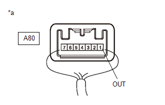
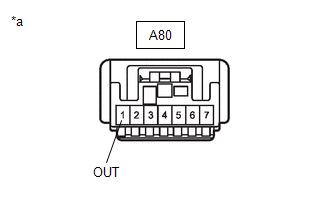
| A80-1 (OUT) - Body ground |
| 1.5 V or less |
| NG | | GO TO STEP 6 |
|
| 4. | CLEAR DTC |
(a) Clear the DTCs.
Click here
|
| 5. | RECONFIRM DTC |
(a) Turn the power switch off.
(b) Turn the power switch on (READY).
(c) Perform a road test.
(d) Check if the same DTC is output.
Click here
| Result | Proceed to |
|---|---|
| DTCs C1425 and P0573 are not output. | A |
| DTCs C1425 and/or P0573 are output. | B |
| A | | USE SIMULATION METHOD TO CHECK |
| B | | REPLACE BRAKE BOOSTER WITH MASTER CYLINDER ASSEMBLY |
| 6. | CHECK STOP LIGHT SWITCH ASSEMBLY |
(a) Turn the power switch off.
(b) Make sure that there is no looseness at the locking part and the connecting part of the connector.
OK:
The connector is securely connected.
| (c) Disconnect the A80 stop light switch assembly connector. |
|
(d) Check both the connector case and the terminals for deformation and corrosion.
OK:
No deformation or corrosion.
(e) Measure the voltage according to the value(s) in the table below.
Standard Voltage:
| Tester Connection | Condition | Specified Condition |
|---|---|---|
| A80-1 (OUT) - Body ground | Stop light switch assembly off (Brake pedal released) | 1.5 V or less |
| OK | | REPLACE STOP LIGHT SWITCH ASSEMBLY |
|
| 7. | CHECK BRAKE BOOSTER WITH MASTER CYLINDER ASSEMBLY |
(a) Make sure that there is no looseness at the locking part and the connecting part of the connector.
OK:
The connector is securely connected.
| (b) Disconnect the A45 skid control ECU (brake booster with master cylinder assembly) connector. |
|
(c) Check both the connector case and the terminals for deformation and corrosion.
OK:
No deformation or corrosion.
(d) Measure the voltage according to the value(s) in the table below.
Standard Voltage:
| Tester Connection | Condition | Specified Condition |
|---|---|---|
| A80-1 (OUT) - Body ground | Stop light switch assembly off (Brake pedal released) | 1.5 V or less |
| OK | | REPLACE BRAKE BOOSTER WITH MASTER CYLINDER ASSEMBLY |
|
| 8. | CHECK FOR SHORT TO +B IN STP CIRCUIT |
(a) Check that there is no short to +B in the STP circuit (wire harnesses, connectors and stop lights).
OK:
No short to +B.
| OK | | USE SIMULATION METHOD TO CHECK |
| NG | | REPAIR OR REPLACE MALFUNCTIONING PART |
| 9. | CHECK HARNESS AND CONNECTOR (STP TERMINAL) |
| (a) Turn the power switch off. |
|
(b) Make sure that there is no looseness at the locking part and the connecting part of the connector.
OK:
The connector is securely connected.
(c) Disconnect the A45 skid control ECU (brake booster with master cylinder assembly) connector.
(d) Check both the connector case and the terminals for deformation and corrosion.
OK:
No deformation or corrosion.
(e) Measure the voltage according to the value(s) in the table below.
Standard Voltage:
| Tester Connection | Condition | Specified Condition |
|---|---|---|
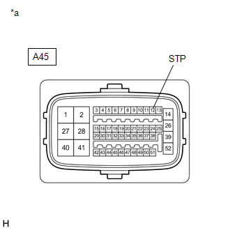
| A45-12 (STP) - Body ground | Stop light switch assembly on (Brake pedal depressed) | 11 to 14 V |
| OK | | REPLACE BRAKE BOOSTER WITH MASTER CYLINDER ASSEMBLY |
| NG | | REPAIR OR REPLACE HARNESS OR CONNECTOR (STP CIRCUIT) |
| 10. | CHECK HARNESS AND CONNECTOR (STOP LIGHT SWITCH ASSEMBLY - STOP LIGHT) |
(a) Check that there is no open in the wire harnesses and connectors from terminal OUT of the stop light switch assembly to the stop lights.
OK:
No open.
| OK | | REPLACE BRAKE BOOSTER WITH MASTER CYLINDER ASSEMBLY |
| NG | | REPAIR OR REPLACE HARNESS OR CONNECTOR (STP CIRCUIT) |
READ NEXT:
 Malfunction in Motor (C1427)
DESCRIPTION When the power switch is on (READY), the stop light switch assembly off and the vehicle speed is 20 km/h (12 mph) or more, the skid control ECU (brake booster with master cylinder assembly
Motor Circuit (C1428)
DESCRIPTION DTC No. Detection Item INF Code DTC Detection Condition Trouble Area MIL Note C1428 Motor Circuit 611 1160
INF Code: 611
An open or short in the ABS motor ci
Steering Angle Sensor Power Source Voltage (C1432)
DESCRIPTION The skid control ECU (brake booster with master cylinder assembly) outputs this DTC when it receives a sensor power source malfunction signal from the steering angle sensor. DTC No. D
SEE MORE:
Removal
REMOVAL CAUTION / NOTICE / HINT The necessary procedures (adjustment, calibration, initialization, or registration) that must be performed after parts are removed and installed, or replaced during knock control sensor removal/installation are shown below. Necessary Procedures After Parts Removed/Ins
Lubrication System
On-vehicle InspectionON-VEHICLE INSPECTION PROCEDURE 1. CHECK ENGINE OIL LEVEL (a) Connect the Techstream to the DLC3. (b) Turn the power switch on (IG). (c) Turn the Techstream on. (d) Put the engine in inspection Mode (Maintenance Mode). Powertrain > Hybrid Control > Utility Tester Displ
