Lexus ES: Steering Angle Sensor Power Source Voltage (C1432)
DESCRIPTION
The skid control ECU (brake booster with master cylinder assembly) outputs this DTC when it receives a sensor power source malfunction signal from the steering angle sensor.
| DTC No. | Detection Item | INF Code | DTC Detection Condition | Trouble Area | MIL | Note |
|---|---|---|---|---|---|---|
| C1432 | Steering Angle Sensor Power Source Voltage | 703 | Steering angle sensor power supply malfunction signal is received from steering angle sensor. |
| Does not come on | VSC DTC |
WIRING DIAGRAM
Refer to DTC C1434.
Click here .gif)
CAUTION / NOTICE / HINT
NOTICE:
Inspect the fuses for circuits related to this system before performing the following procedure.
PROCEDURE
| 1. | CHECK HARNESS AND CONNECTOR (POWER SOURCE TERMINAL) |
| (a) Remove the steering wheel and column cover. |
|
(b) Make sure that there is no looseness at the locking part and the connecting part of the connector.
OK:
The connector is securely connected.
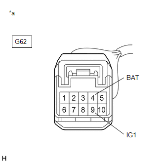
(c) Disconnect the G62 steering angle sensor connector.
(d) Check both the connector case and the terminals for deformation and corrosion.
OK:
No deformation or corrosion.
(e) Measure the voltage according to the value(s) in the table below.
Standard Voltage:
| Tester Connection | Condition | Specified Condition |
|---|---|---|
| G62-4 (BAT) - Body ground | Always | 11 to 14 V |
| G62-9 (IG1) - Body ground | Power switch on (IG) | 11 to 14 V |
| NG |  | REPAIR OR REPLACE HARNESS OR CONNECTOR (POWER SOURCE CIRCUIT) |
|

| 2. | CHECK HARNESS AND CONNECTOR (GND TERMINAL) |
| (a) Turn the power switch off. |
|
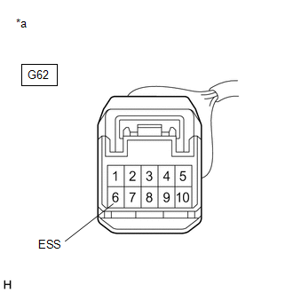
(b) Measure the resistance according to the value(s) in the table below.
NOTICE:
Before measuring the resistance of the steering angle sensor, turn the power switch off and leave the vehicle for 1 minute or more without operating the key or switches, or opening or closing the doors.
Standard Resistance:
| Tester Connection | Condition | Specified Condition |
|---|---|---|
| G62-6 (ESS) - Body ground | 1 minute after power switch off | Below 1 Ω |
| OK | | REPLACE STEERING ANGLE SENSOR |
| NG | | REPAIR OR REPLACE HARNESS OR CONNECTOR (GND CIRCUIT) |
READ NEXT:
 Steering Angle Sensor Internal Circuit (C1433)
DESCRIPTION The skid control ECU (brake booster with master cylinder assembly) outputs this DTC when it receives an internal malfunction signal from the steering angle sensor. DTC No. Detection I
Steering Angle Sensor Output (C1434)
DESCRIPTION Steering angle sensor signals are input to the skid control ECU (brake booster with master cylinder assembly) via the CAN communication system. HINT: When a malfunction occurs in the commu
Malfunction in Yaw Rate Sensor (C1436)
DESCRIPTION The airbag ECU assembly has a built-in yaw rate and acceleration sensor and detects the vehicle condition using 2 circuits (GL1, GL2). When the skid control ECU (brake booster with master
SEE MORE:
On-vehicle Inspection
ON-VEHICLE INSPECTION CAUTION / NOTICE / HINT CAUTION: To prevent injury due to contact with an operating cooling fan, keep your hands and clothing away from the cooling fans when working in the engine compartment with the engine running or the power switch on (IG). PROCEDURE 1. INSPECT ENGINE COOL
Removal
REMOVAL CAUTION / NOTICE / HINT The necessary procedures (adjustment, calibration, initialization, or registration) that must be performed after parts are removed and installed, or replaced during rear combination light assembly removal/installation are shown below. Necessary Procedure After Parts R
